Hummer H1 (2006+). Manual - part 214


  Index      Hummer     Hummer H1 DMAX - service repair manual 2006 year


Search            


Content   ..  212  213  214  215   ..


Hummer H1 (2006+). Manual - part 214


6-6

Wheels and Tires/Central Tire Inflation System (CTIS)

_________________

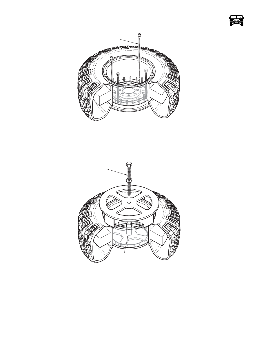
Figure 6-6:   Wheel Separation Bolts

13. Remove the o-ring seal from the inner rim half. Discard the o-ring seal.

14. Assemble the inner bead separator tool (J–45770) by placing the half with the welded center shaft against the o-ring surface of

the inner wheel half and secure with the two bolts and washers provided (Figure  6-7). Place the other half of the tool on the
inner tire bead surface and install the large press bolt through to the threaded hole in the shaft.

Figure 6-7:   Inner Half Bead Separator

15. Rotate the press bolt until the tire bead is released from the inner wheel half. Remove the tool and the inner wheel half from

the tire/runflat assembly.

WARNING:  Balance weights contain lead. Wash hands after handling. 

16. Remove the balance weights from the rim halves. Discard the balance weights.

17. Lay the tire flat.

WARNING:  To avoid injury, ensure run flat compressor strap is centered around run flat.

03-S06-003

SEPARATOR

BOLT

03-S06-004

CENTER

SHAFT

PRESS

BOLT

________________

 Wheels and Tires/Central Tire Inflation System (CTIS)  6-7

5745804

18. Position the run flat compressor on an outer edge of the run flat with the handle assembly facing up and the strap centered

around the run flat(Figure  6-8).

Figure 6-8:   Run Flat Compressor Operation

NOTE: Compress the run flat by rotating the 3/4 nut in a clockwise direction. Rotate the 3/4 nut counterclockwise to loosen.

19. Using a run flat compressor, compress the run flat.

NOTE: It may be necessary to use a tire spoon and tire lube to remove the run flat from the tire. 

20. Remove the run flat from the tire and remove the run flat compressor from the run flat(Figure  6-9).

Figure 6-9:   Run Flat Appearance After Removal

Inspection and Cleaning 

CAUTION: Do not reuse a tire which has been run flat without thoroughly inspecting for damage. Failure to follow these instruc-
tions may result in damage to equipment.

1.

Remove any existing lubricant that has been previously applied to the inside of the tire using a mild detergent soap and water.

2.

Dry all wheel and tire parts. Ensure inside of tire is free of any run flat lubricant, dirt, debris, rust, or moisture.

WARNING:  Thorough tire inspection is critical. Continued use of worn or damaged tires could result in equipment
damage, serious injury or death.

RUN FLAT

RUN FLAT

COMPRESSOR

STRAP

J–42452

COMPRESSOR

02-S06-005

RUN FLAT

TIRE

6-8

Wheels and Tires/Central Tire Inflation System (CTIS)

_________________

3.

Inspect the inside of the tire for cord or belt separation and inner liner damage. Replace the tire if damaged.

4.

Inspect the tire bead for abrasions. Replace the tire if damaged.

5.

Check for protruding objects inside the tire which may not be visible from outside. If the tire is punctured yet repairable, repair
with internal or external tire repair kit.

6.

Check tread depth on the tire. Tread should not be worn below the level of wear bars(Figure  6-10). Markings on the sides of
the tires (e.g., the letters “TWI” or a triangle) show the location of the wear bars. Replace the tire if tread is worn below wear
bars or 3/32 inch (2.38 mm).

7.

Inspect the run flat for splitting, cracking, wear, or excessive chafing. Damaged run flat performance will be non-existent or
greatly reduced. Replace the run flat if damaged (Figure  6-9).

8.

Inspect the outside of the tire for sidewall damage. Replace the tire if damaged. 

9.

Inspect the tread for puncture damage. If damage is too extensive for patch repair, replace the tire.

WARNING:  O-ring sealing surfaces must be kept clean and free from rust and dirt. Failure to do so could cause the
wheel assembly to separate under pressure causing serious injury or death.

10. Using a wire brush, clean the wheel attaching studs. Clean all dirt and foreign material from the rim halves with soap and

water and allow to air dry. Ensure the O-ring sealing surfaces on the rim halves are smooth and clean (Figure  6-5).

11. Inspect the rim halves for cracks, bent sealing surfaces, or oversized mounting holes. Replace the rim halves if cracked, bent,

or if mounting holes are reamed.

Figure 6-10:   Wear Bar Identification

WARNING:  Never use wheel assemblies with wheel half studs that are damaged, loose, or have stripped threads.
Damaged studs can cause improper assembly which could cause individual fasteners to fail. Any of these situations
could cause serious injury or death.

NOTE: When replacing a damaged wheel half stud, also replace the two adjacent studs.

12. Inspect the outer rim half for cracked, broken, corroded, pitted, bent, loose, or stripped studs. Replace damaged studs along

with the two adjacent studs. Failure to do so may result in equipment damage, personal injury or death.

13. Inspect the valve core for cracks or deterioration. Replace the valve core if damaged (Figure  6-5).

14. Inspect the core housing for cracks or deterioration. Replace if damaged.

Repair

1.

If the studs are damaged, drive the studs out of the outer rim half. Discard the studs (Figure  6-11).

2.

Align the stud with the splines in the outer rim and pull the stud into the outer rim using a 1/2-20 nut, a washer and a larger nut
as a spacer until the stud shoulder seats against the outer rim.

02-OM5-002

WEAR BARS

________________

 Wheels and Tires/Central Tire Inflation System (CTIS)  6-9

5745804

Figure 6-11:   Outer Rim Half Stud Removal

Assembly

WARNING:  Never use tubes in the two-piece take-apart wheel assemblies. Use of a tube defeats built-in safety fea-
tures of the wheel, and could cause the wheel to come apart under pressure, resulting in serious injury or death. Use
only replacement parts specified in parts manual. Wheels assembled with components which do not meet specifica-
tions could cause the assembly to separate under pressure, resulting in serious injury or death. To avoid injury en-
sure run flat compressor strap is centered on run flat.

1.

Apply one 11-ounce tube of gel lubricant around the inside of the tire at the crown area. Using a clean brush, evenly spread the
gel lubricant 4 to 5 inches wide on the tire crown area (Figure  6-12).

Figure 6-12:   Run Flat Gel Lubricant Application

2.

Position the run flat compressor on an outer edge of the run flat with the nut facing up and the strap centered around the run
flat (Figure  6-13).

00-S06-007

OUTER

STUDS

WHEEL

HALF

RIM HALF

TIRE

GEL LUBRICANT

4 TO 5 
INCHES

CROWN AREA

OF TIRE


Content   ..  212  213  214  215   ..