Hummer H1 (2006+). Manual - part 201


  Index      Hummer     Hummer H1 DMAX - service repair manual 2006 year


Search            


Content   ..  199  200  201  202   ..


Hummer H1 (2006+). Manual - part 201


5-44

Transmission/Transfer Case

_______________________________________________

SPEED SENSOR AND/OR SWITCH REPLACEMENT

1.

Disconnect the harness connector from the vehicle speed sensor, lock indicator switch, and/or range indicator switch.

2.

Remove the switch and/or sensor from the transfer case.

3.

Install the new switch and/or sensor in the transfer case.

4.

Attach the harness connector to the switch or sensor.

GUIDE CABLE REPLACEMENT

1.

Remove the bolts, nuts, and the washers attaching the cable bracket to the muffler bracket.

2.

Remove the bolts, nuts, and washers securing the guide cable.

3.

Remove the guide cable and bracket.

4.

Attach the guide cable bracket to the muffler bracket.

5.

Attach the guide cable bracket to the transfer case with the washers and nuts.

6.

Install the guide cable and brake line support bracket. Tighten the bracket bolt to 27-33 lb-ft (37-45 N•m).

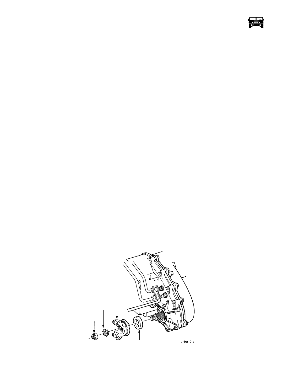
FRONT OUTPUT SHAFT SEAL REPLACEMENT

1.

Mark the front propeller shaft and the transfer case yoke for alignment reference.

2.

Disconnect the front propeller shaft at the yoke. Retain the U-bolts and nuts.

3.

Remove the yoke nut.

4.

Remove the yoke and seal washer. Use tool J–8614-01 to remove the yoke if necessary (Figure  5-22). 

5.

Remove the seal from the front case bore with a standard hook type seal puller.

6.

Coat the outer edge of the new seal with a thin coat of RTV type sealer.

7.

Lubricate the seal lip with transmission fluid and install the seal with tool J–38869.

CAUTION: The seal can be installed incorrectly. Be sure the seal lip is toward the case interior.

8.

Smooth the seal contact surface of the yoke with 320-400 grit emery coated with transmission fluid. Then clean and install the
yoke.

9.

Install the yoke seal washer.

10. Install and tighten the yoke nut to 90-130 lb-ft (122-176 N•m) torque.

11. Connect the propeller shaft to the yoke. Tighten the U-bolt nuts to 13-18 lb-ft (18-24 N•m) torque.

12. Check and top off the transfer case fluid level if necessary.

Figure 5-22:   Front Output Shaft Yoke and Seal Removal/Installation

YOKE

NUT

SEAL

WASHER

YOKE

OIL SEAL

10-1-08

_______________________________________________

 Transmission/Transfer Case  5-45

5745804

TRANSFER CASE FLUID CHANGE

The transfer case fill and drain plugs are both located in the rear of the case (Figure  5-23).

The correct fill level is to the lower edge of the fill plug hole. Recommended fluid is Dexron III.

1.

Place the vehicle on a level surface. Or, if the vehicle is raised on a hoist for fluid change, a drive-on hoist is preferred. The 
vehicle must be level for accurate fluid level.

2.

Remove the drain and fill plugs and drain the fluid into an approved container.

3.

Install and tighten the drain plug to 15-25 lb-ft (20-33 N•m) torque.

4.

Fill the transfer case with Dexron III. Correct level is to the lower edge of the fill plug hole.

5.

Install and tighten the fill plug to 15-25 lb-ft (20-33 N•m) torque.

6.

Lower the vehicle, if on a hoist.

Figure 5-23:   Transfer Case Drain and Fill Plug Locations

TRANSFER CASE REPLACMENT

Removal

1.

Remove the drain plug and drain the oil from the transfer case. Reinstall the drain plug afterward.

2.

Disconnect the propeller shafts from the transfer case.

3.

Disconnect the wiring harness connectors from the vehicle speed sensors, range switch and lock switch.

4.

Remove the wiring harness clamp and move the harness away from the transfer case.

5.

Disconnect the vent line from the transfer case.

6.

Disconnect and plug the cooler hoses at the transfer case.

7.

Disconnect the shift cable at the range lever (Figure  5-24).

8.

Remove the guide cable and bracket.

9.

Support the transfer case with a jack. Secure the transfer case to the jack with chain.

10. Remove the nuts attaching the transfer case to the transmission adapter.

11. Slide the transfer case rearward and remove it from under the vehicle.

FILL

PLUG

DRAIN

PLUG

10-1-08

5-46

Transmission/Transfer Case

_______________________________________________

Figure 5-24:   Shifter Cable Attachment

TRANSFER CASE

RANGE LEVER

T CASE 

SHIFTER CABLE

10-1-08

_______________________________________________

 Transmission/Transfer Case  5-47

5745804

Installation

1.

Mount the transfer case on a jack and secure it with a chain.

2.

Apply a bead of Loctite 518 to the mounting surface of the transmission adapter.

3.

Align and install the transfer case on the transmission. Tighten the transfer case attaching nuts to 37 lb-ft (50 N•m).

4.

Remove the jack.

5.

Connect the shift cable to the transfer case range lever (Figure  5-24).

6.

Install the guide cable and bracket.

7.

Connect the transfer case vent line.

8.

Connect the cooler hoses to the transfer case cooler fittings.

9.

Connect the front and rear propeller shafts to the transfer case. Tighten the front shaft U-bolt nuts to 13-18 lb-ft (18-24 N•m)
torque.

10. Install the vehicle speed sensor wire connector.

11. Install the range indicator switch wire connector.

12. Attach the harness clamp to the transfer case.

13. Connect the wiring harness connectors to the speed sensor and switches.

14. Fill the transfer case to the bottom edge of the fill plug hole with Dexron III.

15. Check and adjust the shift cable if necessary.

TRANSFER CASE DISASSEMBLY AND OVERHAUL

1.

Remove the vehicle speed sensor and both of the indicator switches.

2.

Remove the front output shaft yoke (Figure  5-25). Remove the yoke nut with a suitable size socket, and impact wrench. Then
remove the seal, washer, and the yoke.

Figure 5-25:   Front Yoke Removal/Installation

3.

Remove the extension housing bolts. Then tap the housing counter clockwise to break the sealer bead (Figure  5-26). Use a
plastic mallet to tap the housing.

4.

Remove the extension housing (Figure  5-27).

SEAL

WASHER

YOKE

NUT

YOKE

FRONT

OUTPUT

SHAFT

10-1-08


Content   ..  199  200  201  202   ..