Hummer H1 (2006+). Manual - part 158


  Index      Hummer     Hummer H1 DMAX - service repair manual 2006 year


Search            


Content   ..  156  157  158  159   ..


Hummer H1 (2006+). Manual - part 158


OBD-476

On-Board Diagnostics

_____________________________________________

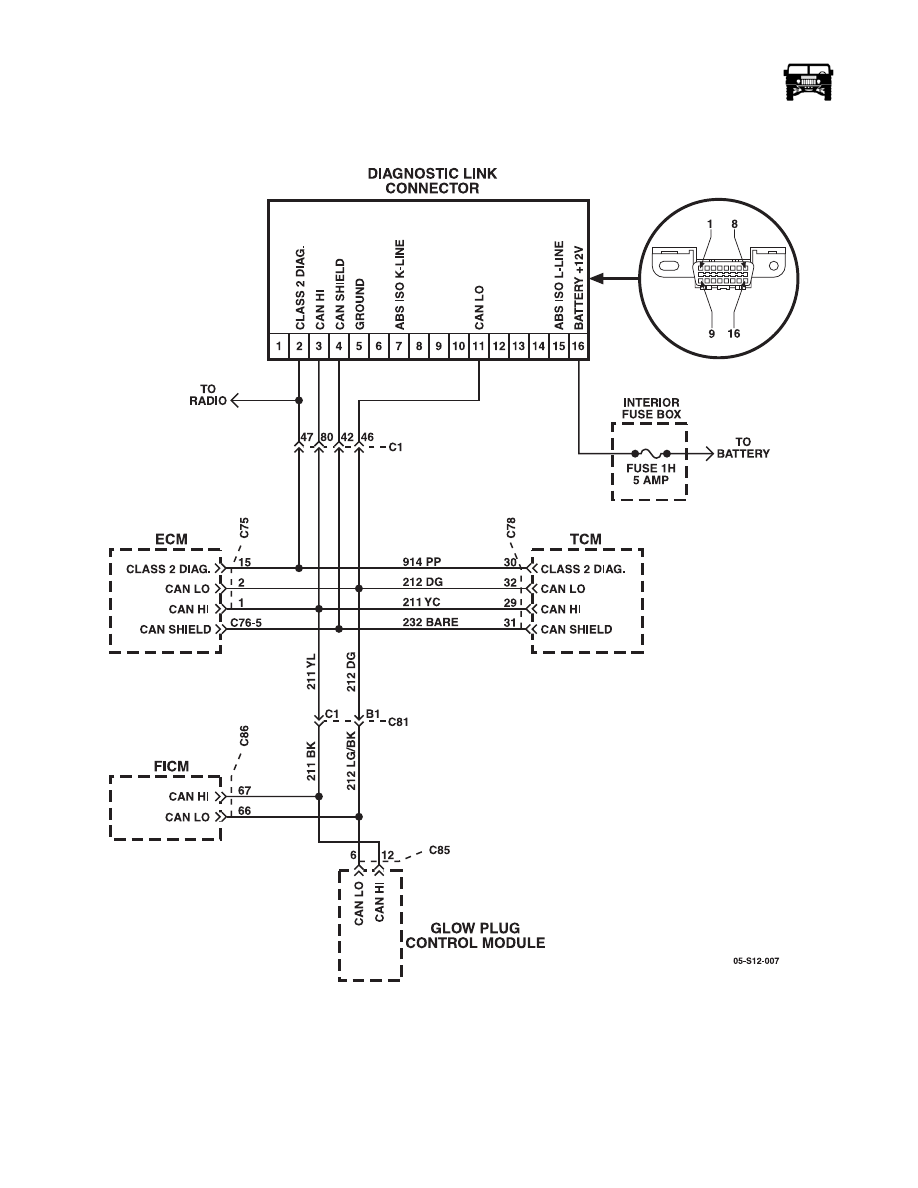
DTC U0100-U299 Lost Communication With Engine Control Module (ECM) (Figure OBD-121)

Figure OBD-121:   CAN Communication Bus Circuit

Circuit Description

Modules connected to the controller area network (CAN) serial data circuits monitor for serial data communications during normal
vehicle operation. Operating information and commands are exchanged among the modules. The modules have prerecorded infor-
mation about what messages are needed to be exchanged on the serial data circuits. The messages are supervised and also, some

_____________________________________________

 On-Board Diagnostics  OBD-477

5745804

periodic messages are used by the receiver module as an availability indication of the transmitter module. Each message contains
the identification number of the transmitter module. A module with a CAN serial data circuits malfunction or which loses power
during the current ignition cycle will have a Loss of Communication DTC set by other modules that depend on information from
that failed module. If any of the CAN circuits are shorted to battery voltage, ground or between them, no communication is possi-
ble on CAN serial data bus, and a DTC U0073 is set.

Conditions for Setting the DTC

A supervised periodic message that includes the transmitter module availability has not been received.

Action Taken When the DTC Sets 

• The module uses a default value for the missing parameter. 

• The malfunction indicator lamp (MIL) will illuminate on the second consecutive ignition cycle that the diagnostic runs and 

fails, for the type B DTCs. For a detailed description about DTC types, refer to Diagnostic Trouble Code (DTC) Type 
Definitions in Engine Controls - 6.6L (LLY). 

Conditions for Clearing the MIL/DTC

The MIL/DTC clearing depends on DTC type. For information about DTC types, refer to Diagnostic Trouble Code (DTC) Type(s)
in Engine Controls - 6.6L (LLY).

• DTC type B 

•  The MIL clears after 3 ignition cycles when the malfunction is no longer present. 

•  A current DTC clears when the malfunction is no longer present. 

•  A history DTC clears when the module ignition cycle counter reaches the reset threshold, without a repeat of the mal-

function.

Diagnostic Aids 

• A poor connection at the inoperative module may cause this code to set. 

• An improperly powered module may cause this code to set. 

Step

Action

Value(s)

Yes

No

    1

Did you perform the Diagnostic System Check - Vehicle?

Go to Step 2

Go to Diagnos-

tic System 

Check

    2

1.

Install a scan tool.

2.

Start the engine.

3.

Retrieve DTCs from engine control module (ECM).

Is DTC U0073 set as current?

Go to DTC 

U0073

Go to Step 3 

OBD-478

On-Board Diagnostics

_____________________________________________

    3

NOTE: Use the DTC descriptor list in order to determine which
module is not communicating on controller area network (CAN)
serial data bus.

1.

Turn the ignition ON, with the engine OFF.

2.

Test the following circuits of the module that is not commu-
nicating on CAN serial data bus for an open or a short to 
ground:

• The battery positive voltage input circuits 

• The battery positive voltage output circuits 

• The ignition voltage input circuits 

• The ignition voltage output circuits 

• The switched battery positive voltage circuits 

Refer to the following:

• Control Module References for the applicable schematic 

• Circuit Testing in Wiring Systems 

• Wiring Repairs in Wiring Systems 

Did you find and correct the condition?

Go to Step 9 

Go to Step 4

    4

1.

Turn OFF the ignition.

2.

Test the ground circuits of the module that is not communi-
cating on CAN serial data bus for an open.

Refer to the following:

• Control Module References for the applicable schematic 

• Circuit Testing in Wiring Systems 

• Wiring Repairs in Wiring Systems 

Did you find and correct the condition?

Go to Step 9

Go to Step 5

    5

Test the CAN serial data circuits of the module that is not com-
municating on CAN serial data bus for an open. 

Did you find and correct the condition?

Go to Step 9 

Go to Step 6

    6

Inspect the harness connectors of the module that is not commu-
nicating on CAN serial data bus for poor connections and termi-
nal tension at the following circuits:

• The battery positive voltage input circuits 

• The battery positive voltage output circuits 

• The ignition voltage input circuits 

• The ignition voltage output circuits 

• The switched battery positive voltage supply circuits 

• The ground circuits 

• The CAN serial data circuits 

Refer to the following:

• Control Module References for the applicable schematic 

• Testing for Intermittent Conditions and Poor Connections 

in Wiring Systems 

• Connector Repairs in Wiring Systems 

Go to Step 9

Go to Step 7

Step

Action

Value(s)

Yes

No

_____________________________________________

 On-Board Diagnostics  OBD-479

5745804

CONNECTOR LEGEND

102 WAY BULKHEAD  LOCATION: LEFT SIDE FIREWALL

    7

Replace the module that is not communicating on CAN serial
data bus. 

Did you complete the replacement?

Go to Step 8

    8

1.

Install a scan tool.

2.

Turn ON the ignition with the engine OFF.

3.

Select the Display DTCs function for the module which was 
not communicating.

Does the scan tool display any DTCs which do not begin with a
"U"?

Go to Diagnos-

tic Trouble 

Code

Go to Step 9 

    9

Select the Display DTCs function for the modules which had the
Loss of Communications DTC set.

Does the scan tool display any DTCs which do not begin with a
"U"?

Go to Diagnos-

tic Trouble 

Code

Go to Step 10 

    10

1.

Use the scan tool in order to clear the DTCs.

2.

Continue diagnosing or clearing the DTCs until all the mod-
ules have been diagnosed and all the DTCs have been 
cleared.

Did you complete the action?

System OK

PIN

CKT

COLOR

CIRCUIT DESCRIPTION

1

739

PP

Left heated windshield power +

2

740

YL

Right heated windshield power +

3

16

LG

Ignition relay signal +

Step

Action

Value(s)

Yes

No

Connector C1 


Content   ..  156  157  158  159   ..