Hummer H1 (2006+). Manual - part 33


  Index      Hummer     Hummer H1 DMAX - service repair manual 2006 year


Search            


Content   ..  31  32  33  34   ..


Hummer H1 (2006+). Manual - part 33


2-38

Engine

______________________________________________________________________

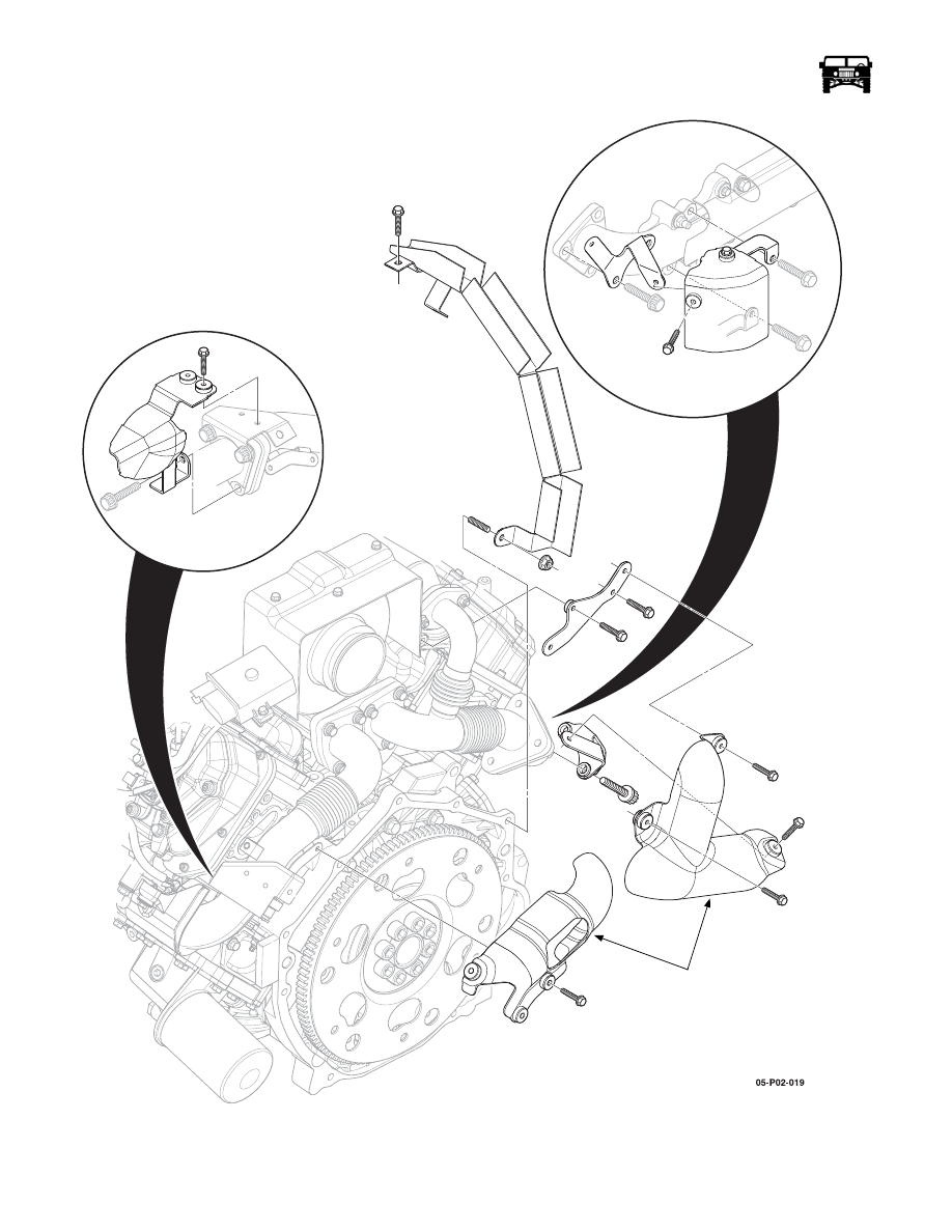
Figure 2-33:   Turbo Pipe Heat Shields

TURBO PIPE

HEAT SHEILDS 

______________________________________________________________________

 Engine  2-39

5745804

CYLINDER HEAD AND GASKET SERVICE

Cylinder Head (Left Side)

Removal

1.

Disconnect and isolate the negative battery cable.

2.

Drain the cooling system.

3.

Remove the thermostat housing crossover (Refer to section 4).

4.

Remove the left intake manifold  (See “Intake Manifold” on page 2-43) .

5.

Remove the left exhaust manifold  (See “Exhaust Manifold Service” on page 2-36) .

6.

Remove the valve rocker arm shaft, pushrods and valve bridges  (See “Valve Rocker Arm Shaft and Push Rod Replacement”
on page 2-30) .

7.

Remove the glow plugs (Refer to section 12).

8.

Remove the cylinder head bolts in the sequence shown (Figure  2-35).

9.

Discard the large M12 bolts.

10. Remove the cylinder head (Figure  2-36).

11. Remove the cylinder head gasket note the size of the gasket from the indicators in (Figure  2-34) and from the cylinder head

gasket selection chart in (Figure  2-37).

Figure 2-34:   Head Gasket Size Indicators

12. Clean the sealing surface of the engine block and the cylinder head.

NOTE: þClean all dirt, debris and coolant from the engine block cylinder head bolt holes. Failure to remove all foreign material
may result in damaged threads, improperly tightened fasteners or damage to components.

13. Clean the cylinder head bolt holes in the engine block.

2-40

Engine

______________________________________________________________________

Figure 2-35:   Cylinder Head Removal and Torque Sequence

Figure 2-36:   Cylinder Head and Gasket Removal/Installation.

Cylinder Head (Left Side)

Installation

NOTE: þThe left and right cylinder head gaskets are not interchangeable. Improper placement of the cylinder head gasket will
block coolant and oil passages. Blocked coolant and oil passages will cause severe engine damage.

1.

Install the cylinder head gasket of the correct grade (Figure  2-37).

2.

Install the cylinder head.

NOTE: þThis component uses bolts with a preapplied molybdenum disulfide coating for thread lubrication. Do not remove the
coating or use any additional lubricant. Improperly lubricated threads will adversely affect the bolt torque and clamp load. Im-
proper bolt torque and clamp load can lead to engine damage.

3.

Install NEW M12 cylinder head bolts. 

4.

Reuse the M8 cylinder head bolts.

5.

Torque the cylinder head bolts in the following steps using the sequence shown (Figure  2-35).

a.

Tighten the M12 bolts a first pass to 50þN·m (37þlbþft).

b.

Tighten the M12 bolts a second pass to 80þN·m (59þlbþft)

2

13

17

4

21

3

20

16

1

12

8

7

11

15

19

22

18

14

10

6

5

9

CYLINDER HEAD

DOWEL

CYLINDER HEAD

GASKET

______________________________________________________________________

 Engine  2-41

5745804

c.

Tighten the M12 bolts a third pass to 90þdegrees, using J–45059.

d.

Tighten the M12 bolts a final pass to 75þdegrees, using J–45059.

e.

Tighten the M8 bolts to 25þN·m (18þlbþft).

6.

Install the valve rocker arm shaft, pushrods and valve bridges and adjust the valves.

7.

Install the glow plugs.

8.

Install the exhaust manifold

9.

Install the intake manifold.

10. Install the thermostat housing crossover.

11. Fill and bleed the cooling system.

12. Connect the negative battery cable.

13. Road test the vehicle for normal operation.

14. Inspect for coolant, oil or exhaust leaks.

Figure 2-37:   Cylinder Head Gasket Selection Specifications

Cylinder Head (Right Side)

Removal 

1.

Disconnect and isolate the negative battery cable.

2.

Drain the cooling system.

3.

Remove the thermostat housing crossover (Refer to section 4).

4.

Remove the right intake manifold (Refer to section 2).

5.

Remove the right exhaust manifold (Refer to section 2).

6.

Remove the valve rocker arm shaft, pushrods and valve bridges (Refer to section 2).

7.

Remove the glow plugs (Refer to section 12).

8.

Remove the cylinder head bolts in the sequence shown (Figure  2-35).

9.

Discard the large M12 bolts.

10. Remove the cylinder head.

11. Remove the cylinder head gasket note the size of the gasket from the indicators in (Figure  2-34) and from the cylinder head

gasket selection chart in (Figure  2-37).

12. Clean the sealing surface of the engine block and the cylinder head.

NOTE: þClean all dirt, debris and coolant from the engine block cylinder head bolt holes. Failure to remove all foreign material
may result in damaged threads, improperly tightened fasteners or damage to components.

13. Clean the cylinder head bolt holes in the engine block.

 Cylinder Head Gasket Selection Specifications

Ti max (Piston Projection)

Gasket Thickness

Cylinder Head Gasket Grade

Metric (mm)

English (in)

Metric 

(mm)

English 

(in)

Grade A (No grade hole on the 
gasket)

Over 0.223 - less than 0.274

Over 0.0088 - less than 0.0108

0.90-1.00

0.0354-

0.0394

Grade B (One grade hole on the 
gasket)

Over 0.274 - less than 0.325

Over 0.0108 - less than 0.0128

0.95-1.05

0.0374-

0.0413

Grace C (Two grade holes on the 
gasket)

Over 0.325 - less than 0.376

Over 0.0128 - less than 0.0148

1.00-1.10

0.0394-

0.0433


Content   ..  31  32  33  34   ..