Hummer H1 (2002+). Manual - part 252


  Index      Hummer     Hummer H1 - service repair manual 2002 year


Search            


Content   ..  250  251  252  253   ..


Hummer H1 (2002+). Manual - part 252


_______________________________________________________________________________


 13-1


®


05745159


Section 13   Accessories


TABLE OF CONTENTS


Air Restriction Gauge . . . . . . . . . . . . . . . . . . . . . . . . . . . . . . . .13-34
Auxiliary Seat

Belt Replacement. . . . . . . . . . . . . . . . . . . . . . . . . . . . . . . .13-27
Frame Replacement. . . . . . . . . . . . . . . . . . . . . . . . . . . . . .13-28
Locking Pin Replacement . . . . . . . . . . . . . . . . . . . . . . . . .13-28
Replacement. . . . . . . . . . . . . . . . . . . . . . . . . . . . . . . . . . . .13-27

Brushguard Assembly Replacement   . . . . . . . . . . . . . . . . . . .13-10
Delco Compact Disc Changer Replacement . . . . . . . . . . . . . .13-36
Dual Oil Filter . . . . . . . . . . . . . . . . . . . . . . . . . . . . . . . . . . . . . . .13-35
Hourmeter. . . . . . . . . . . . . . . . . . . . . . . . . . . . . . . . . . . . . . . . . .13-30
Off Road Light Package  . . . . . . . . . . . . . . . . . . . . . . . . . . . . . .13-31
Roof Rack

Clamp Replacement. . . . . . . . . . . . . . . . . . . . . . . . . . . . . .13-26
Crossbar Replacement . . . . . . . . . . . . . . . . . . . . . . . . . . .13-25
End Replacement. . . . . . . . . . . . . . . . . . . . . . . . . . . . . . . .13-25

Running Board Replacement . . . . . . . . . . . . . . . . . . . . . . . . . .13-21
Seat Heater . . . . . . . . . . . . . . . . . . . . . . . . . . . . . . . . . . . . . . . . .13-37

Spare Tire Carrier

Cargo Deck Mounted  . . . . . . . . . . . . . . . . . . . . . . . . . . . . 13-13
Swing-Away . . . . . . . . . . . . . . . . . . . . . . . . . . . . . . . . . . . . 13-10

Trailer Hitch Replacement . . . . . . . . . . . . . . . . . . . . . . . . . . . . 13-20
Trailer Towing Connector. . . . . . . . . . . . . . . . . . . . . . . . . . . . . 13-19
Underbody Protection

Front Shield Replacement  . . . . . . . . . . . . . . . . . . . . . . . . 13-15
Intermediate Shield Replacement . . . . . . . . . . . . . . . . . . 13-16
Rear Shield Replacement . . . . . . . . . . . . . . . . . . . . . . . . . 13-17
Skid Plate Replacement . . . . . . . . . . . . . . . . . . . . . . . . . . 13-14
Transfer Case Shield Replacement . . . . . . . . . . . . . . . . . 13-17

Rocker Panel Protection Replacement . . . . . . . . . . . . . . . . . . 13-18
Winch

Assembly Repair . . . . . . . . . . . . . . . . . . . . . . . . . . . . . . . . . 13-3
Cable Replacement . . . . . . . . . . . . . . . . . . . . . . . . . . . . . . . 13-2
Electric Thermal Switch/Brush Assembly  . . . . . . . . . . . . 13-7
Replacement  . . . . . . . . . . . . . . . . . . . . . . . . . . . . . . . . . . . . 13-1
Troubleshooting  . . . . . . . . . . . . . . . . . . . . . . . . . . . . . . . . . 13-1


WINCH  VIN 186477 AND LATER


NOTE: 


Individual parts may not be available for some of the

following repair procedures. Assemblies must be used in place
of individual parts. Check for parts availability before disas-
sembly.


Winch Troubleshooting


Winch Inoperative


1.

Check for jammed winch cable.

2.

Check winch control cable connector for corrosion or
loose connection. Clean corroded connector or secure
loose connection.

3.

Check for loose or damaged winch power cables. Using
voltmeter, connect positive meter lead to positive power
cable (red) at the winch motor, and negative meter lead to
the winch motor ground cables (black). If voltage is not
present, repair or replace winch power cables.

4.

Disconnect winch control from winch. Using an
ohmmeter, check for continuity between the common
terminal and the other two terminals on winch control
cable connector. Check for continuity one at a time, while
holding control in the OUT position and the IN position. If
continuity is present in both positions, repair winch. If
continuity is not present in both positions, replace winch
control.


Winch Replacement


Removal 


WARNING:  To avoid personal injury or damage, sup-
port winch during removal.


1.

Disconnect battery ground cables (Section 12).

2.

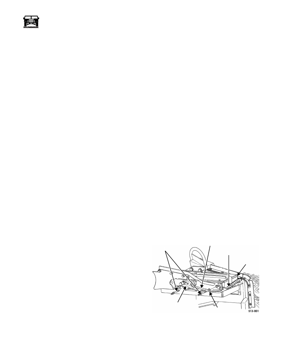
Remove two battery cable bolts, battery cables, and winch
cables from battery  (Figure 13-1).


Figure 13-1:    Winch Cables On Battery 


3.

Remove nut, lockwasher, capscrew, and clamp from right
frame extension. Discard lockwasher. Pull winch cables
through the splash shield to front of vehicle (Figure 13-2). 

POSITIVE

BATTERY

NEGATIVE

POSITIVE

BATTERY CABLE

 BATTERY 

CABLE

 WINCH 

CABLE

NEGATIVE

WINCH CABLE

BATTERY CABLE

BOLTS


13-2

Accessories


_______________________________________________________________


®


Figure 13-2:   Frame Bracket


4.

Remove four nuts, washers, bolts, and winch from front
bumper (Figure 13-3).


Figure 13-3:    Winch and Winch Cables 


5.

Remove two bolts and clamps securing winch cables to
winch.

6.

Remove bolt and control box cover from winch.

7.

Remove capscrew, washer, and negative winch cable from
winch.

8.

Remove bolt and positive winch cable from winch. 


Installation 


1.

Install positive winch cable on winch with bolt (Figure 13-3).

2.

Install negative winch cable on winch with washer and
capscrew.

3.

Coat motor end of winch with coating compound. 

4.

Install control box cover on winch with bolt.

5.

Secure two winch cables to winch with two clamps and bolts. 

6.

Install winch on front bumper with four washers, bolts,
and nuts. Tighten bolts to 60 lb-ft (81 N•m).

7.

Route winch power cables through the splash shield.

8.

Install winch cables on frame bracket with clamp,
capscrew, lockwasher, and nut (Figure 13-2).

9.

Connect battery ground cables (Section 12).


Winch Cable Replacement 


WARNING:  To avoid injury, wear gloves when han-
dling winch cable.


Removal 


1.

Unwind winch cable.

2.

Remove set screw and winch cable/hook assembly from
drum assembly (Figure 13-4).


Figure 13-4:   Winch Cable 


Installation 


3.

Install winch cable/hook assembly on drum assembly with
set screw.


CAUTION: 


Install winch cable on drum under a load of at

least 500 lb (227 kg), or outer wraps will draw into
 inner wraps and damage cable.


NOTE: 


Spool winch cable according to rotation label on

winch or brake will not function.

4.

Rewind and lubricate winch cable.

CLAMP

FRAME BRACKET

POWER CABLES

CLAMP

POSITIVE 

CONTROL 

NEGATIVE

FRONT BUMPER

WINCH

BOX 

COVER

WINCH 

CABLE

 WINCH 

CABLE

SET SCREW 

CABLE ANCHOR

CABLE/HOOK 

ASSEMBLY


______________________________________________________________


 Accessories  13-3


®


05745159


Winch Assembly Repair


Disassembly 


1.

Remove winch and winch cable.


NOTE: 


Tag leads for assembly.

2.

Remove three nuts and control leads from motor
 (Figure 13-5).


Figure 13-5:    Control Leads 


3.

Loosen clamps and remove control from motor
(Figure 13-6).


Figure 13-6:    Control Unit 


4.

Remove clamps from motor.

5.

Mark motor end drum support, gear train assembly, and
gear end drum support for assembly (Figure 13-7).


Figure 13-7:    Drum Support and 

Gear Train Assembly


6.

Remove six bolts, three tie rods and gear end drum support
from winch.

7.

Remove motor, and motor end drum support from drum
assembly. 

8.

Remove motor brake driver and spacer from motor shaft.

9.

Remove drum assembly from gear train assembly
(Figure 13-7).

10. Remove two nylon thrust washers from drum

(Figure 13-8).


Figure 13-8:   Thrust Washers and Brake

00-S13-005

LEAD

CONTROL

DRUM SUPPORT

NUT

MOTOR

00-S13-006

CONTROL

CLAMP

MOTOR

MOTOR

(SHOWN WITHOUT CONTROL)

SPACER (2)

DRUM SUPPORT

BRAKE 

BRAKE 

DRUM

ASSEMBLY

DRIVER

 MOTOR END

DRUM SUPPORT

 GEAR END

TIE ROD

GEAR TRAIN

ASSEMBLY

NYLON THRUST

WASHER

BRAKE 

DRUM

NYLON THRUST

WASHER

SET SCREW

BRAKE RETENTION

NOT REMOVABLE

ASSEMBLY

SPACER

BRAKE

DRIVER


13-4

Accessories


_______________________________________________________________


®


11. Loosen set screw that retains brake. 

12. Push brake through open end of drum and remove

(Figure 13-8).

13. Remove driveshaft from gear train assembly

(Figure 13-9).

14. Turn gear train assembly over with gear end drum support

down. Remove ten hex-head screws and gear housing
from gear end drum support.

15. Remove gasket from gear end drum support. Discard

gasket  (Figure 13-9). 


Figure 13-9:    Gear Train Assembly


16. Remove detent spacer, spring, and detent ball from gear

housing (Figure 13-10).


Figure 13-10:   Gear Housing


17. Remove clutch lever and O-ring seal from gear housing.

Discard O-ring seal. 

18. Remove two retaining rings from gear housing

(Figure 13-10).


NOTE: 


Intermediate ring gear comes out with 85 to 87 steel

balls. Be sure to catch all 85 to 87 steel balls.

19. Remove intermediate ring gear and 85 to 87 steel balls

from gear housing.

20. Remove input and intermediate gear carrier assembly from

gear housing  (Figure 13-10).

21. Remove  and output gear carrier from output ring gear and

gear end drum support (Figure 13-11)

.


Figure 13-11:    Gear Carriers


22. Remove output ring gear and gasket from gear end drum

support.


Cleaning 


CAUTION: 


To avoid damage to equipment, do not clean brake

assembly. Clean and inspect all winch components. Replace
defective parts.

GEAR TRAIN ASSEMBLY

GASKET

GEAR HOUSING

DRIVESHAFT

GEAR END

DRUM SUPPORT

O-RING

CLUTCH

LEVER

DETENT

BALL

SPRING

DETENT

SPACER

STEEL BALLS

GEAR

RETAINING

RINGS

INTERMEDIATE 

RING

GEAR

SUN 

INPUT

 CARRIER

GEAR

 HOUSING

INTERMEDIATE

GEAR

CARRIER

INTERMEDIATE

GEAR CARRIER

OUTPUT

RING GEAR

GASKET

GEAR END

DRUM SUPPORT


Content   ..  250  251  252  253   ..