Hummer H1 (2002+). Manual - part 55
____________________________________________
Transmission/Transfer Case 5-19
®
05745159
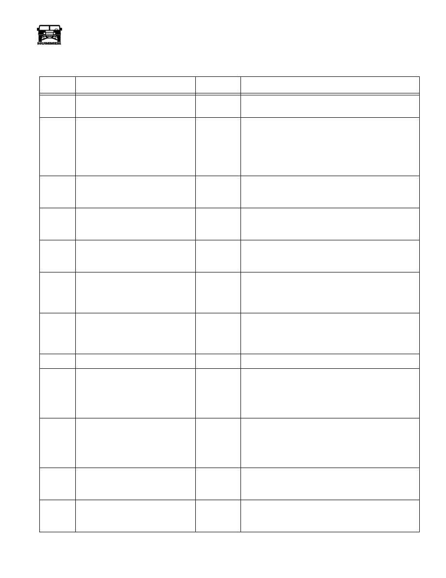
Trouble Code Identification
DTC
Description
DTC Type
Default Action
P0218
Transmission Fluid Overtemperature
D
1.
The PCM freezes shift adapts.
2.
DTC P0218 is stored in PCM history.
P0560
Sysem Voltage Malfunction
D
1.
The PCM inhibits TCC engagement.
2.
The PCM freezes shift adapts.
3.
The PCM turns off the PC Sol. Valve.
4.
The PCM commands an immediate landing into 2nd
gear.
5.
DTC P0560 is stored in PCM history.
P0711
Transmission Fluid Temperature Sen-
sor Circuit Range/Performance
D
1.
The PCM uses a TFT default value of 140° C (284°F).
2.
The PCM freezes shift adapts.
3.
DTC P0711 is stored in the PCM history.
P0712
Transmission Fluid Temperature Sen-
sor Circuit Low Input
D
1.
The PCM freezes shift adapts.
2.
The PCM uses a TFT default value of 140° C (284°F).
3.
DTC P0712 is stored in PCM history.
P0713
Transmission Fluid Temperature Sen-
sor Circuit High Input
D
1.
The PCM freezes shift adapts.
2.
The PCM uses a TFT default value of 140° C (284°F).
3.
DTC P0713 is stored in PCM history.
P0716
Input Speed Sensor Circuit Intermit-
tent
B
1.
The PCM illuminates the MIL.
2.
The PCM freezes shift adapts.
3.
The PCM commands maximum line pressure
4.
DTC P0716 is stored in PCM history.
P0717
Input Speed Sensor Circut Low Input
B
1.
The PCM illuminates teh MIL.
2.
The PCM freezes shift adapts.
3.
The PCM commands maximum line pressure.
4.
DTC P0717 is stored in PCM history.
P0719
Brake Switch Circuit Low Input
D
DTC P0719 is stored in PCM history.
P0722
Output Speed Sensor Low Input
B
1.
The PCM illuminates the MIL.
2.
The PCM freezes shift adapts
3.
The PCM commands maximum line pressure.
4.
The PCM calculates the OSS from the ISS.
5.
DTC P0722 is stored in the PCM history.
P0723
Output Speed Sensor Intermittent
B
1.
The PCM illuminates the MIL.
2.
The PCM freezes shift adapts
3.
The PCM commands maximum line pressure.
4.
The PCM calculates the OSS from the ISS.
5.
DTC P0723 is stored in the PCM history.
P0724
Brake Switch Circuit High Input
D
1.
Apply TCC if APP is greater than 0.5% and the vehi-
cle speed is greater than 30 mph.
2.
DTC P0724 is stored in PCM history.
P0730
Incorrect gear ratio
D
1.
The PCM commands maximum line pressure.
2.
The PCM freezes shift adapts.
3.
DTC P0730 is stored in PCM history.