Hummer H1 (2002+). Manual - part 46
___________________________________________
Fuel, Emissions, and Exhaust 3-45
®
5745159
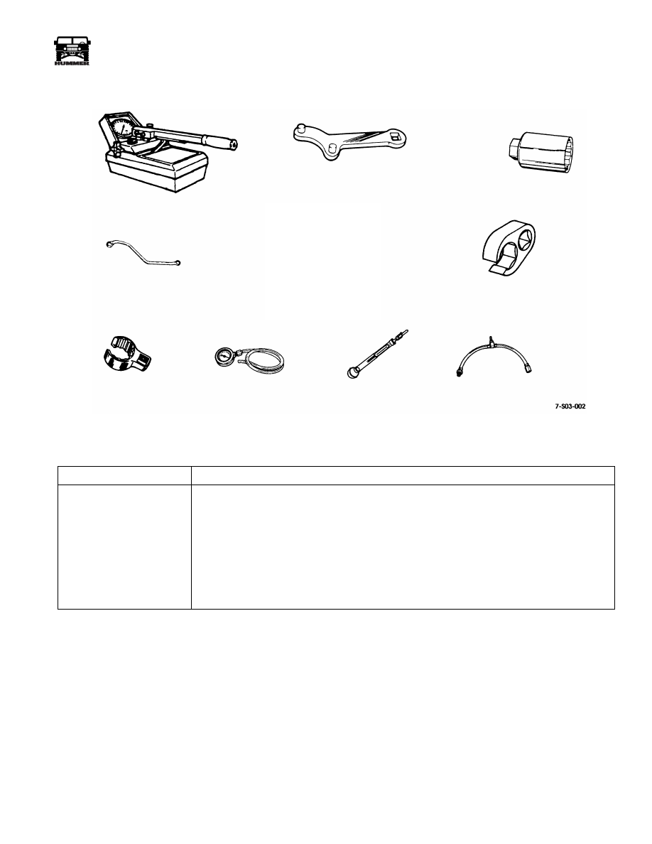
ESSENTIAL TOOLS
Procure from Kent-Moore.
Tool No.
Description
J–29075-AMG
Fuel Injector Pressure Test Tool
J–29872-A
Injection Pump Adjusting Tool (used with ratchet handle)
J–29873
Fuel Injector Socket (30mm)
J–29698-A
Injection Line (flare nut) Wrench, 3/4
J–28552-A
Fuel Pressure Gauge
J–38641-B
Diesel Fuel Hydrometer
J–34151
Housing Pressure Adapter
J–41711
Injection Pump Timing Wrench, 6.5 Turbo (not shown)
J–28552-100
Adapter, Fuel Line
J–29075-AMG
J–29872-A
J–29873
J–41089
J–29079-125
J–41516-A
J–29698-A
J–28552-A
J–38641-B
J–34151