Hummer H1 (2002+). Manual - part 16


  Index      Hummer     Hummer H1 - service repair manual 2002 year


Search            


Content   ..  14  15  16  17   ..


Hummer H1 (2002+). Manual - part 16


____________________________________________________________________

 Engine  2-25

¨

05745159

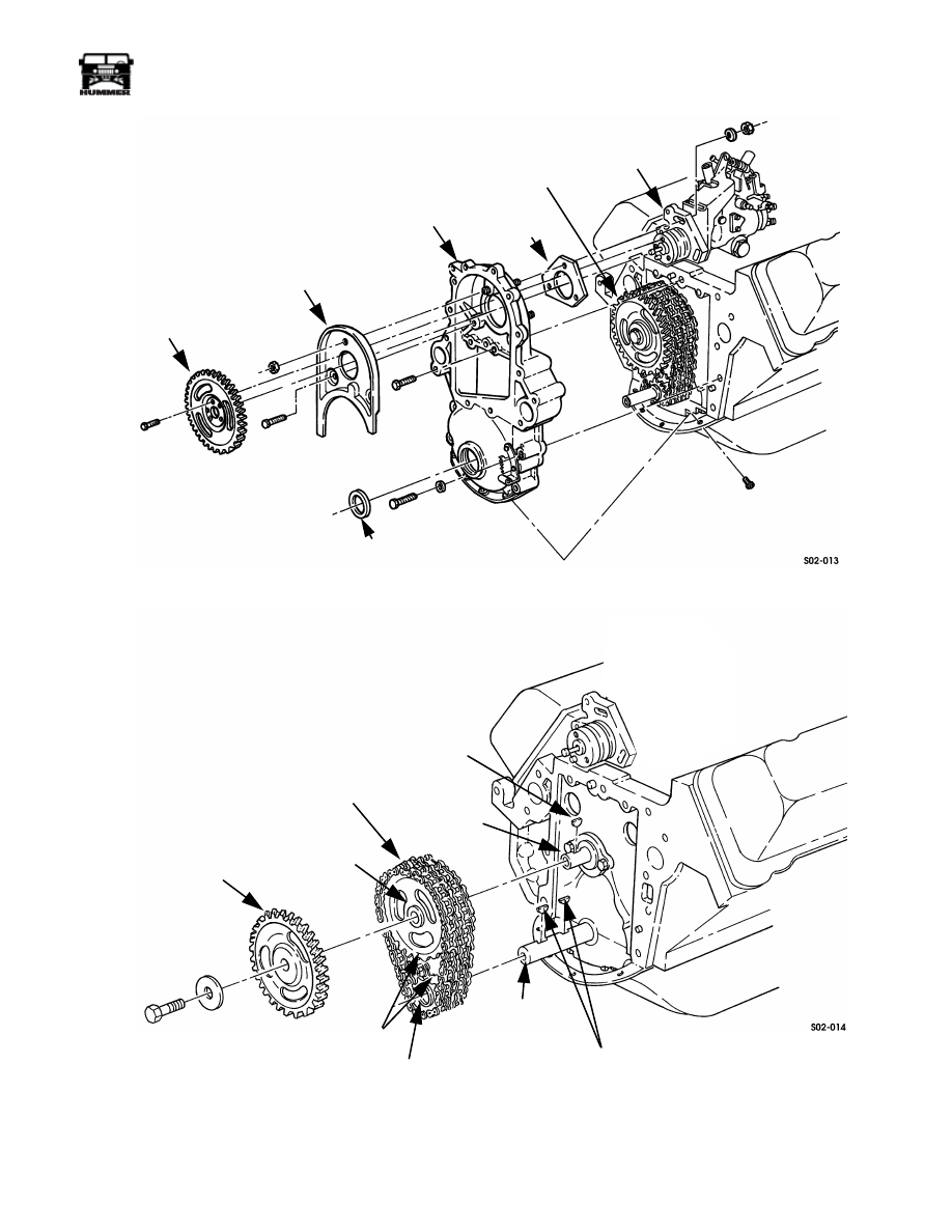
Figure 2-24:   Drive Gear, Baffle, and Front Cover Removal

Figure 2-25:   Drive Gear, Timing Chain, and Sprocket Removal

FRONT

SEAL

BAFFLE

INJECTION

PUMP

DRIVEN

GEAR

FRONT
COVER

PUMP

GASKET

FUEL 

PUMP

INJECTION

PUMP

DRIVE

GEAR

INJECTION

INJECTION PUMP

DRIVE GEAR

CAMSHAFT 

TIMING CHAIN

CAMSHAFT KEY

CAMSHAFT

CRANKSHAFT

CRANKSHAFT KEYS

CRANKSHAFT

SPROCKET

TIMING MARKS

SPROCKET

2-26

Engine

_____________________________________________________________________

¨

Front Cover Installation

1.

Install new camshaft thrust plate and spacer if required.

2.

Clean front cover and engine block sealing surfaces with
carb cleaner and wipe dry.

3.

Install drive keys in camshaft and crankshaft. Be sure keys
are seated.

4.

Assemble and install timing chain and sprockets
(Figure 

2-26). Check timing mark alignment before

proceeding.

5.

Install injection pump drive gear on camshaft
(Figure 2-26). Timing mark on gear should be facing
upward (12 oÕclock position). Then install drive gear
attaching washer and bolt. Tighten bolt to 55-60 lb-ft (75-
81 N¥m) torque.

Figure 2-26:   Timing Chain, Sprockets, and Drive 

Gear Installation

6.

Install new seal in front cover with tool J

Ð

22102.

7.

Apply sealer to front cover as follows:

¥

Use anerobic sealer, such as Loctite 510, on cover 
surfaces that contact engine block.

¥

Use RTV-type sealer, such as Loctite 592, on oil pan 
and oil pan contact surface of front cover.

¥

Refer to sealer application diagram  (Figure 2-27).

Figure 2-27:   Front Cover Sealer Application 

Diagram

8.

Install front cover on engine block (Figure 2-28). Be sure
cover is fully seated on engine block dowels, engine
block, and oil pan, before installing cover bolts.

9.

Install front cover attaching bolts. Then tighten bolts as
follows:

¥

Tighten cover-to-engine block bolts to 33 lb-ft (45 
N¥m) torque.

¥

Tighten oil pan-to-front cover bolts to 4-10 lb-ft (5-14 
N¥m) torque.

10. Install injection pump gasket on front cover studs

 (Figure 2-28:).

INJECTION PUMP

DRIVE GEAR

TIMING CHAIN

CRANKSHAFT

SPROCKET

CAMSHAFT

SPROCKET

CRANKSHAFT

DRIVE KEYS

CAMSHAFT

THRUST PLATE

AND SPACER

FRONT COVER

USE ANEROBIC

SEALER HERE

USE RTV TYPE

SEALANT HERE

(OIL PAN CONTACT

SURFACE)

____________________________________________________________________

 Engine  2-27

¨

05745159

Figure 2-28:   Front Cover Mounting

11. Install baffle in front cover (Figure 

2-29). Maintain

minimum clearance of 0.040 in. (1.02 mm) between baffle
and injection pump drive gear. Tighten baffle attaching
bolts/nuts to 33 lb-ft (45 N¥m) torque.

12. Install fuel injection pump driven gear on pump shaft as

follows:

a.

Align timing marks on drive and driven gears and in-
stall driven gear on pump shaft.

b.

Verify timing mark alignment. Drive gear mark 
should be at 12 oÕclock position and driven gear mark 
at 6 oÕclock position.

NOTE:  If timing marks are not perfectly aligned, turn the
pump shaft to correct alignment. Do not turn the gears.

c.

Install and tighten driven gear attaching bolts to 13-20 
lb-ft (18-27 N¥m) torque.

13. Check alignment of timing marks on front cover and

injection pump flange. Rotate pump to align if necessary.
Then install pump attaching nuts.

14. Secure fuel injection pump to front cover. Tighten pump

attaching nuts to 13-20 lb-ft (18-27 N¥m) torque.

15. Lubricate front cover seal lip with engine oil, or petroleum

jelly. Then lubricate seal contact surface of torsional
damper with engine oil. Be sure seal contact surface of
damper is smooth and free of burrs, nicks, or corrosion.

16. Install damper drive key in crankshaft slot. Be sure key is

fully seated.

Figure 2-29:   Baffle and Pump Driven Gear 

Installation

17. Install torsional damper. Then install damper attaching

washer and bolt. Tighten bolt to 140-160 lb-ft (190-217
N¥m) torque.

18. Install crankshaft pulley. Tighten pulley bolts to 48 lb-ft

(65 N¥m) torque.

19. Install coolant crossover and oil filler neck. Tighten

crossover bolts to 31 lb-ft (42 N¥m) torque and filler neck
attaching nut to 13-20 lb-ft (18-27 N¥m) torque.

20. Apply bead of anaerobic sealer, such as Loctite 510, to

water pump and adapter plate. Refer to Figure 2-36 for
sealer application.

21. Install water pump and adapter plate. Apply Permatex/

Loctite pipe sealing compound, to fastener that goes in
hole ÒAÓ (Figure 2-30). Tighten pump/adapter bolts to 13-
20 lb-ft (18-27 N¥m) torque.

Figure 2-30:   Water Pump Adapter Plate Sealer 

Application Diagram

DOWEL

DOWEL

INJECTION PUMP

PUMP

GASKET

FRONT

COVER

INJECTION PUMP
DRIVEN GEAR

TIMING MARK

BAFFLE

FRONT COVER

APPLY 

HERE

SEALANT

APPLY 

HERE

SEALANT

FASTENER HOLE “A”

2-28

Engine

_____________________________________________________________________

¨

22. Install fan pulley, fan, and fan clutch. Tighten attaching

nuts to 15-20 lb-ft (20-27 N¥m).

23. Install serpentine drive belt.

24. Connect heater and bypass hoses at water pump and

crossover. Then attach radiator upper inlet hoses to inlet
tube.

25. Install radiator and shroud (Figure 2-21). Then install air

conditioning condenser and power steering fluid cooler.

26. Connect radiator upper and lower hoses.

27. Fill cooling system.

28. Connect battery negative cables.

29. Evacuate and recharge air conditioning system if

necessary.

30. Start and run engine to verify proper operation. Purge air

from cooling system (if necessary), and top off coolant
level at surge tank.

31. On turbo diesel, reprogram TDC offset. Refer to procedure

at end of this section. 

OIL PUMP SERVICE 

Removal

1.

Drain engine oil and remove oil Þlter.

2.

Remove oil pan bolts.

3.

Tap oil pan with rubber mallet to break sealer bead. Use
putty knife to help separate sealer bead if necessary. Then
remove pan.

4.

Loosen screw that secures bracket on oil pump pickup
tube.

5.

Remove nut that secures tube bracket to oil pump
mounting stud (Figure 2-31). Then rotate bracket off stud.

6.

Remove oil pump mounting stud (Figure 2-31).

7.

Remove oil pump and pump shaft.

Inspection And Replacement

The oil pump can be disassembled for inspection but not re-
paired. The oil pump is only serviced as an assembly. Individ-
ual parts are not available.

Replace the pump if the oil pickup strainer and tube are loose,
cracked, or distorted. Also replace the pump if the housing is
damaged or the pump gears are worn, chipped, or cracked.

Check the pump shaft and pressure relief valve and spring. Re-
place the pump if the spring is collapsed or broken, the valve is
damaged, the retaining pin is loose, or damaged, or the pump
shaft is worn or damaged.

The oil pickup strainer can be cleaned with spray-type carb
cleaner if necessary. However, replace the pump if heavy accu-
mulations of oil sludge, grit, foreign material, or metal chips
are present.

Figure 2-31:   Oil Pump Mounting

Installation

1.

Prime oil pump. Pour about four ounces of engine oil into 
pump through strainer and rotate shaft to coat gears. 

2.

Insert pump shaft into block. Then align and seat pump.

3.

Install and tighten pump mounting stud to 59-74 lb-ft (80-
100 N¥m) torque.

4.

Rotate pickup tube bracket onto pump mounting stud.
Then install and tighten bracket retaining nut to 35 lb-ft
(47 N¥m).

5.

Tighten clamp screw on pickup tube bracket to 12 lb-ft
(16 N¥m) torque.

6.

Clean oil pan and engine block sealing surfaces with
scraper and solvent. Final clean surfaces with brake or
electrical contact cleaner to remove all residue. Otherwise,
RTV sealer will not adhere properly.

7.

Apply RTV-type sealer to front cover, oil pan, and engine
pan rail surfaces. Sealers such as Permatex ultra copper, or
black are equally acceptable.

8.

Install rear seal in oil pan.

9.

Position oil pan on engine and front cover. Then install
and tighten oil pan bolts as follows:

¥

Tighten rear two bolts to 89 lb-in (10 N¥m) torque.

¥

Tighten remaining bolts to 17 lb-ft (23 N¥m) torque.

10. Install oil filter and refill with recommended grade engine

oil.

BRACKET

TUBE

STRAINER

PUMP

MOUNTING

STUD

OIL PUMP

PUMP SHAFT


Content   ..  14  15  16  17   ..