Honda Ridgeline. Manual - part 330
 

  Index      Honda     Honda Ridgeline - service repair manual 2006-2008 year


Search            


Content   ..  328  329  330  331   ..


Honda Ridgeline. Manual - part 330


90

−

−

−

−

+

+

−

+

−

+

−

+

−

−

−

−

−

−

+

+

−

−

19-57

GND

1

2

1

2

1

2

2

1

IC

IC

VSA1

NO

NC

NC

NO

VSA2

IN

OUT

RIGHT FRONT

LEFT FRONT

OUT

IN

IN

OUT

LEFT REAR

RIGHT REAR

OUT

IN

VCC

B

IG1

IG1

44

B SOL

WHT/RED

41

RL GND

RED

RL

B

YEL/RED

FR GND

16

BLU

20

21

BLU/WHT

42

FL B

BRN/WHT

FL GND

GRN/BLK

FR B

17

VCC

11

S GND

YEL/BLK

4

2

5

1

YEL/BLK

GRN/WHT

WHT

RED

RED

RED

WHT

WHT

GRN/WHT

YEL/BLK

4

1

2

3

IG1

40

GRN/WHT

A8

WHT/BLK

PCM

A36

A1

WHT

33

CAN H

RED

12

CAN L

CONTROL UNIT

VSA MODULATOR CONTROL UNIT

7

MODULATOR UNIT

IG1

15

K LINE

LT BLU

RR GND

18

BLU/YEL

RR

B

19

GRN/YEL

WHT/RED

26

FLP

LT GRN

28

FRP

GRY/YEL

RLP

RRP

5

GRY/RED

WHT

B MOT

45

46

GND1

BLK

BLK

GND2

43

G302

VTM 4
CONTROL UNIT

5 V
REGULATOR

PRESSURE
SENSOR

CAN
CONTROLLER

YAW RATE
LATERAL
ACCELERATION
SENSOR

STEERING
ANGLE
SENSOR

VALVE
RELAY

PUMP MOTOR
RELAY

FRONT
WHEEL SENSOR

REAR
WHEEL SENSOR

(cont’d)

01

19-58

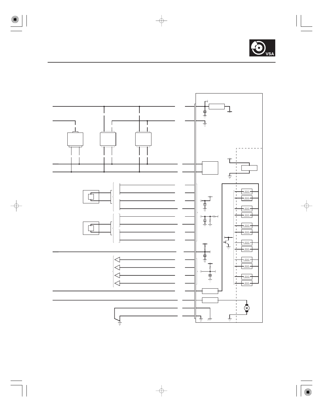
VSA System Components

Circuit Diagram (cont’d)

DATA LINK CONNECTOR (16P)

REAR

WHEEL SENSOR 2P CONNECTOR

PCM CONNECTOR A (44P)

FRONT

BRAKE PEDAL POSITION
SWITCH 4P CONNECTOR

GAUGE CONTROL MODULE
CONNECTOR B (14P)

VSA OFF SWITCH
10P CONNECTOR

STEERING ANGLE SENSOR
5P CONNECTOR

VSA MODULATOR-CONTROL UNIT 46P CONNECTOR

YAW RATE-LATERAL ACCELERATION
SENSOR 4P CONNECTOR

Terminal side of female terminals

Wire side of female terminals

Terminal side of male terminals

Wire side of female terminals

+

+

+

+

+

+

+

+

+

+

01

02

SJC8A00K80100081110FAAT00

+

+

+

+

+

+

+

+

−

−

+

−

−

+

−

−

DTC 11, 13, 15, 17:

YES

NO

DTC

Appropriate Terminal

B

GND

YES

NO

DTC

Appropriate Terminal

B

GND

YES

NO

19-59

DTC Troubleshooting

FL-GND
(BRN/WHT)

RL

B (YEL/RED)

FL

B

(BLU/WHT)

RR

B (GRN/YEL)

RL-GND
(RED)

FR-GND (BLU)

FR

B (GRN/BLK)

VSA MODULATOR-CONTROL UNIT 46P CONNECTOR

RR-GND (BLU/YEL)

FL-GND
(BRN/WHT)

RL

B (YEL/RED)

FL

B

(BLU/WHT)

RR

B (GRN/YEL)

RL-GND
(RED)

FR-GND (BLU)

FR

B (GRN/BLK)

VSA MODULATOR-CONTROL UNIT 46P CONNECTOR

RR-GND (BLU/YEL)

Wheel Sensor (Open/Short

to Body Ground/Short to Power)

1. Clear the DTCs with the HDS (see page 19-41).

2. Turn the ignition switch OFF, then turn it ON (II).

3. Check for DTCs with the HDS (see page 19-41).

Go to step 4.

Intermittent failure, the system is OK at this

time. Check for loose or poor connections.

4. Turn the ignition switch OFF.

5. Disconnect the VSA modulator-control unit 46P

connector.

6. Turn the ignition switch ON (II).

7. Measure voltage between body ground and the

appropriate wheel sensor

B and GND terminals

of the VSA modulator-control unit 46P connector
individually (see table).

11 (Right-front)

FR

B:

No. 17

FR-GND:

No. 16

13 (Left-front)

FL

B:

No. 42

FL-GND:

No. 21

15 (Right-rear)

RR

B:

No. 19

RR-GND:

No. 18

17 (Left-rear)

RL

B:

No. 20

RL-GND:

No. 41

Repair short to power in the wire between

the VSA modulator-control unit and the appropriate
wheel sensor.

Go to step 8.

8. Turn the ignition switch OFF.

9. Check for continuity between body ground and the

appropriate wheel sensor

B and GND terminals

of the VSA modulator-control unit 46P connector
individually (see table).

11 (Right-front)

FR

B:

No. 17

FR-GND:

No. 16

13 (Left-front)

FL

B:

No. 42

FL-GND:

No. 21

15 (Right-rear)

RR

B:

No. 19

RR-GND:

No. 18

17 (Left-rear)

RL

B:

No. 20

RL-GND:

No. 41

Go to step 10.

Go to step 12.

(cont’d)

Wire side of female terminals

Wire side of female terminals

Does the ABS indicator come on and ar e DT C 11,
13, 15, and/ or 17 indicated?

Is ther e 0.2 V or mor e?

Is ther e continuity?

+

+

+

+

+

+

+

+

+

+

03

04

+

+

+

+

+

+

+

+

+

−

−

+

−

−

DTC

Appropriate Terminal

B

GND

YES

NO

DTC

Appropriate Terminal

B

GND

YES

NO

19-60

VSA System Components

DTC Troubleshooting (cont’d)

FL-GND
(BRN/WHT)

RL

B (YEL/RED)

FL

B

(BLU/WHT)

RR

B (GRN/YEL)

RL-GND
(RED)

FR-GND (BLU)

FR

B (GRN/BLK)

VSA MODULATOR-CONTROL UNIT 46P CONNECTOR

RR-GND (BLU/YEL)

VSA MODULATOR-CONTROL UNIT 46P CONNECTOR

FL-GND
(BRN/WHT)

RL

B (YEL/RED)

FL

B

(BLU/WHT)

RR

B (GRN/YEL)

RL-GND (RED)

FR-GND (BLU)

FR

B (GRN/BLK)

RR-GND (BLU/YEL)

10. Disconnect the appropriate wheel sensor 2P

connector.

11. Check for continuity between body ground and the

appropriate wheel sensor

B and GND terminals

of the VSA modulator-control unit 46P connector
individually (see table).

11 (Right-front)

FR

B:

No. 17

FR-GND:

No. 16

13 (Left-front)

FL

B:

No. 42

FL-GND:

No. 21

15 (Right-rear)

RR

B:

No. 19

RR-GND:

No. 18

17 (Left-rear)

RL

B:

No. 20

RL-GND:

No. 41

Repair short to body ground in the wire

between the VSA modulator-control unit and the
appropriate wheel sensor.

Replace the appropriate wheel sensor

(see page 19-97).

12. Disconnect the appropriate wheel sensor 2P

connector.

13. Check for continuity between the appropriate

wheel sensor

B and GND terminals of the VSA

modulator-control unit 46P connector (see table).

11 (Right-front)

FR

B:

No. 17

FR-GND:

No. 16

13 (Left-front)

FL

B:

No. 42

FL-GND:

No. 21

15 (Right-rear)

RR

B:

No. 19

RR-GND:

No. 18

17 (Left-rear)

RL

B:

No. 20

RL-GND:

No. 41

Repair short in the wires between the VSA

modulator-control unit and the appropriate wheel
sensor.

Go to step 14.

Wire side of female terminals

Wire side of female terminals

Is ther e continuity?

Is ther e continuity?


Content   ..  328  329  330  331   ..