Honda Odyssey 2004. Manual - part 580
−
−
−
−
02
03
04
05
YES
NO
YES
NO
23-262
SRS
DTC Troubleshooting (cont’d)
A
A
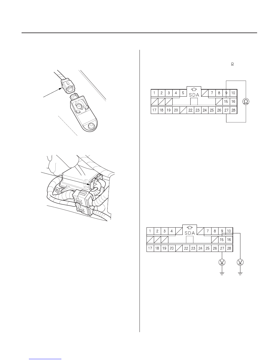
SRS UNIT CONNECTOR A (28P)
RED
BRN/BLK
SRS UNIT CONNECTOR A (28P)
RED
BRN/
BLK
8. Disconnect the engine compartment left wire
harness 2P connector (A) from the left front impact
sensor.
9. Disconnect SRS unit connector A (28P) from the
SRS unit.
10. Check resistance between the No. 15 and No. 27
terminals of SRS unit connector A (28P). There
should be an open circuit, or at least 1 M
.
Go to step 11.
Go to step 17.
11. Reconnect the battery negative cable.
12. Turn the ignition switch ON (II).
13. Check for voltage between the No. 27 terminal of
SRS unit connector A (28P) and body ground, and
between the No. 15 terminal and body ground.
There should be 1 V or less.
Go to step 14.
Go to step 19.
Wire side of female terminals
Wire side of female terminals
Is the r esistance as specif ied?
Is the voltage as specif ied?
03/07/29 10:39:35 61S0X050_230_0262