Honda Odyssey 2004. Manual - part 576
−
−
−
−
03
*01
05
YES
NO
YES
NO
23-246
SRS
DTC Troubleshooting (cont’d)
LEFT SIDE WIRE HARNESS
2P CONNECTOR
07XAZ-S1A0200
C852
A
GRN/YEL
GRN
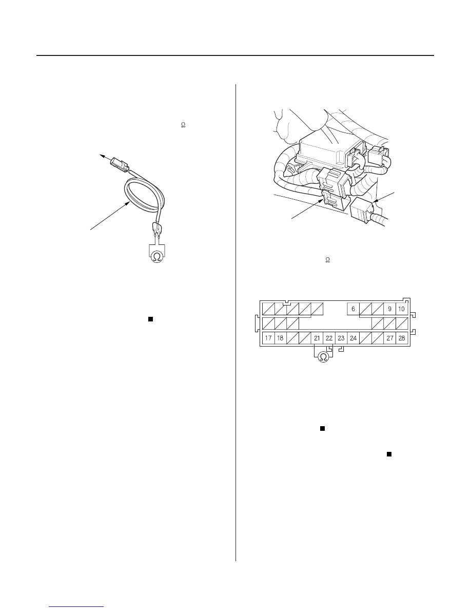
SRS FLOOR HARNESS 28P CONNECTOR
12. Disconnect the SRS inflator simulator from SRS
simulator lead E.
13. Check resistance between the terminals of SRS
simulator lead E. There should be 1.0
or less.
Faulty SRS unit or poor contact at SRS unit
connector B (28P) and the SRS unit. Check the
connection; if the connection is OK, replace the
SRS unit (see page 23-384).
Go to step 14.
14. Disconnect the SRS floor harness 28P connector (A)
from SRS floor subharness C852.
15. Check resistance between the No. 21 and No. 22
terminals of the SRS floor harness 28P connector.
There should be 1.0
or less.
Open or increased resistance in the SRS
floor subharness or left side wire harness; replace
the faulty harness.
Open or increased resistance in the SRS floor
harness; replace the SRS floor harness.
Terminal side of male terminals
Is the r esistance as specif ied?
Is the r esistance as specif ied?
03/07/29 10:38:12 61S0X050_230_0246