Honda Odyssey 2004. Manual - part 519
01
S0X4AZ4H46400000000DAAT00
[
]
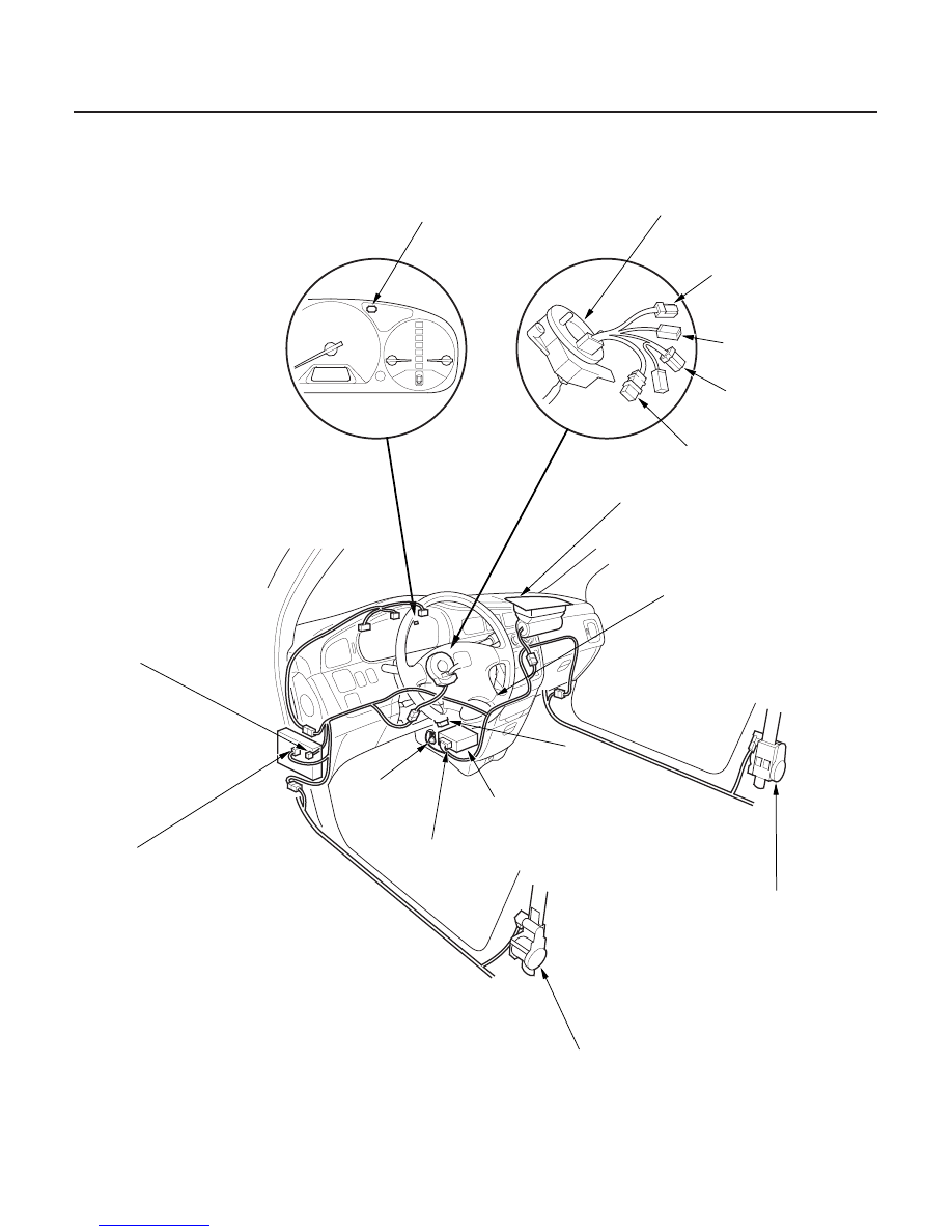
’99-01 Models
23-18
SRS
Component Location Index
SRS INDICATOR
CABLE REEL
To HORN SWITCH
To CRUISE CONTROL
SET/RESUME SWITCH
To DRIVER’S AIRBAG
FRONT PASSENGER’S AIRBAG
MEMORY ERASE SIGNAL
(MES) CONNECTOR (2P)
GRN, GRN
SRS MAIN HARNESS
to SRS UNIT
18P CONNECTOR
SRS UNIT
GROUND
SRS UNIT
DATA LINK
CONNECTOR
(DLC) (16P)
SRS MAIN HARNESS
to DRIVER’S UNDER-DASH
FUSE/RELAY BOX
2P CONNECTOR
To RADIO REMOTE
SWITCH
DRIVER’S SEAT BELT TENSIONER
FRONT PASSENGER’S SEAT
BELT TENSIONER
DRIVER’S AIRBAG
Troubleshooting, page 23-337
Replacement, page 23-376
Replacement, page 23-370
Disposal, page 23-373
Replacement, page 23-382
Replacement, page 23-4
Disposal, page 23-373
Replacement, page 23-4
Disposal, page 23-373
Replacement, page 23-368
Disposal, page 23-373
03/07/29 10:30:46 61S0X050_230_0018