Honda Odyssey 2004. Manual - part 485
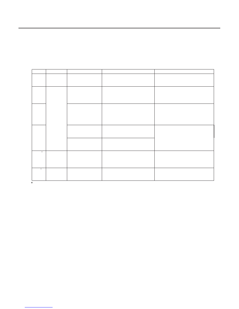
Cavity
Wire
Test condition
Test: Desired result
Possible cause if result is not obtained
22-268
Power Door Locks/Factory Keyless/Factory Security
Control Unit Input Test (cont’d)
4. With the driver’s multiplex cotrol unit still disconnected, make these input tests at the connector and fuse/relay
box sockets.
• If any test indicates a problem, find and correct the cause, then recheck the system.
• If all the input tests prove OK, go to step 5.
•
•
•
•
•
•
•
•
•
•
•
•
•
•
•
B11
BLK
Under all
conditions
Check for continuity to
ground:
There should be continuity.
Poor ground (G501)
An open in the wire
A12
Fuse/relay
box socket
Under all
conditions
Check for voltage to ground:
There should be battery
voltage.
Blown No. 13 (7.5A) fuse or
faulty passenger’s under-dash
fuse/relay box
An open in the wire
A24
Ignition switch ON
(II)
Check for voltage to ground:
There should be battery
voltage.
Blown No. 9 (7.5A) fuse in the
driver’s under-dash fuse/relay
box
Faulty driver’s under-dash fuse/
relay box
A22
Combination light
switch ON
Check for continuity to
ground:
There should be continuity.
Poor ground (G401)
Faulty combination light switch
An open in the wire
Combination light
switch OFF
Check for continuity to
ground:
There should be no continuity.
B16
RED/GRN
Combination light
switch ON and
jump battery
voltage to B16
Check the exterior lights:
The taillights and parking
lights should come on.
Faulty taillight relay
Faulty combination light switch
An open in the wire
K4
RED/BLU
Under all
conditions
Attach to ground:
The indicator should come on.
Faulty security indicator
Faulty gauge assembly
An open in the wire
: ’01-04 EX and ’02-04 EXL models
03/07/29 10:25:51 61S0X050_220_0270