Honda Odyssey 2004. Manual - part 412
*01
S0X4A12G44200000000EAAT00
−
−
−
−
−
−
−
−
21-124
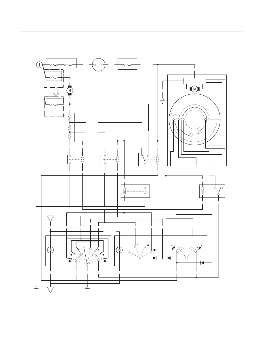
Rear Heater-A/C
Circuit Diagram
No.42 (50A)
BATTERY
No.41 (120A)
No.60 (40A)
UNDER HOOD FUSE/RELAY BOX
No.80 (40A)
(’03 04 models)
RED/BLK
YEL/RED
GRN/YEL
GRN/WHT
5
BLK/YEL
10
BLU/YEL
7
(HOT)
(COOL)
YEL/BLU
8
YEL/RED
9
GRN/RED
1
WHT/RED
2
3
RED/BLU
BLU/BLK
4
7
8
4
6
LIGHT
RED
OFF
1
(HOT)
(COOL)
BLK
G582
GRN/YEL
BLU/YEL
BLK
G582
1
BLK/YEL
6
4
YEL/BLU
3
BRN/YEL
2
5
3
GRN/WHT
2
1
BLK
RED/BLU
BLK/YEL
BLK/YEL
1
YEL/RED
3
WHT/RED
4
5
BLK/YEL
2
GRN/RED
GRN/WHT
BLU/YEL
RED
YEL/BLU
G401
BLK
6
5
3
9
WHT/RED
GRN/RED
RED/BLU
BLU/BLK
4
RR
LIGHT
OFF
2
4
BLK/YEL
1
3
BLU/BLK
BLK
WHT/RED
BLK
1
2
GRN/YEL
BLU/YEL
BLU/YEL
3
6
1
2
BLK/YEL
10
5
4
2
1
RED/BLK
RED
3
5
2
1
WHT
YEL
BLK/YEL
No.3 (7.5A)
IG2
BAT
IGNITION SWITCH
IG2 HOT in ON (II)
DRIVER’S UNDER DASH
FUSE/RELAY BOX
MULTI FUSE/
RELAY BOX
REAR
BLOWER
MOTOR
(’99 02
models)
REAR
BLOWER
MOTOR
LOW
RELAY
REAR
BLOWER
MOTOR
MIDDLE
RELAY
REAR
BLOWER
MOTOR
MAIN
RELAY
DRIVING
CIRCUIT
REAR MODE
CONTROL MOTOR
REAR
BLOWER
MOTOR
HIGH
RELAY
REAR
MODE
CONTROL
MOTOR
RELAY
COMBINATION
LIGHT SWITCH or
TAILLIGHT RELAY
REAR
HEATER A/C
MAIN SWITCH
REAR HEATER A/C PASSENGER’S
CONTROL PANEL
MULTIPLEX
CONTROL UNIT,
DRIVER’S
UNDER HOOD
SUB FUSE
BOX
REAR BLOWER
RESISTOR
03/07/29 10:14:09 61S0X050_210_0125