Honda Odyssey 2004. Manual - part 336
−
−
−
−
−
−
02
13
01
S0X4A96K70200081360FAAT10
YES
NO
YES
NO
YES
NO
TCS DTC 36:
19-150
19-150
ABS/TCS Components
DTC Troubleshooting (cont’d)
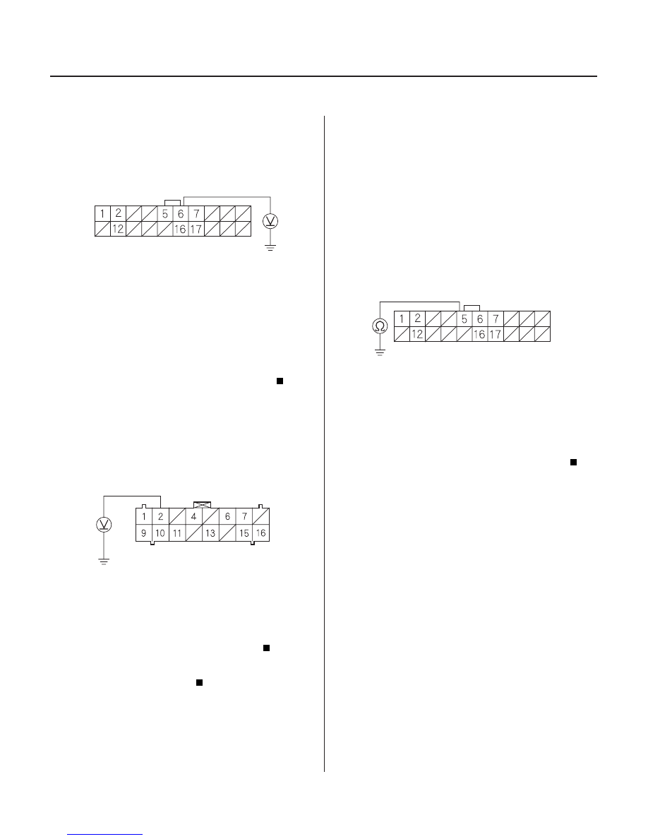
PCM CONNECTOR E (20P)
VREF (WHT/RED)
ABS/TCS CONTROL UNIT CONNECTOR B (16P)
VREF (WHT/RED)
PCM CONNECTOR E (20P)
THLOUT (RED/BLK)
5. Measure the voltage between the PCM connector
terminal No. 6 and body ground.
Go to step 6.
Check for loose PCM connectors. If necessary,
substitute a known-good PCM, and recheck.
6. Measure the voltage between the ABS/TCS control
unit connector B(16P) terminal No. 2 and body
The system is OK at this time. If the problem
recurs, replace the ABS/TCS control unit.
Repair open in the wire between the PCM and
the ABS/TCS control unit.
NOTE: If the MIL or ABS indicator is ON, troubleshoot
the PGM-FI or ABS first.
1. Disconnect the PCM connector E (20P) and the ABS/
TCS control unit connector B(16P).
2. Check for continuity between the PCM connector E
(20P) terminal No. 5 and body gound.
Repair short to body ground in the wire
between the PCM and the ABS/TCS control unit.
Go to step 3.
3. Connect the PCM connector E (20P).
4. Start the engine.
Throttle Position Sensor Output
(THLOUT) Signal (’02-04 models)
Wire side of female terminals
Wire side of female terminals
Wire side of female terminals
Is ther e about 5 V ?
Is ther e about 5 V ?
Is ther e continuity?
03/07/29 09:57:58 61S0X050_190_0150
ground.