Honda Odyssey 2004. Manual - part 275
−
−
−
−
02
02
*02
Special Tools Required
Grease quantity
Inboard joint:
Left Driveshaft: 180
200 g (6.3
7.1 oz)
Right Driveshaft:165
185 g (5.8
6.5 oz)
Inboard Joint Side
16-10
Driveline/Axle
Driveshaft Reassembly (cont’d)
A
A
B
E
D
D
C
• Boot band tool, KD-3191 or equivalent, commercially
available
• Boot band pincers, Kent-Moore J-35910 or equivalent,
commercially available
NOTE: Refer to the Exploded View as needed during
this procedure.
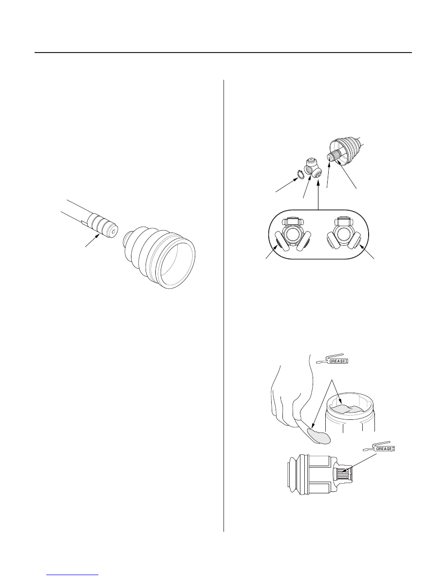
1. Wrap the splines with vinyl tape (A) to prevent
damage to the inboard boot.
2. Install the inboard boot to the driveshaft, then
remove the vinyl tape. Be careful not to damage the
inboard boot.
3. Install the spider (A or B) onto the driveshaft (C) by
aligning the marks (D) on the spider and the end of
the driveshaft.
NOTE: The spider (A) is for the left driveshaft;
spider (B) is for the right driveshaft.
4. Install the snap ring (E).
5. Pack the inboard joint with the joint grease
included in the new driveshaft set.
Use the grease included
in the inboard boot set.
03/07/29 09:47:27 61S0X050_160_0010