Honda Odyssey 2004. Manual - part 191


  Index      Honda     Honda Odyssey 2004 - service repair manual 2004 year


Search            


Content   ..  189  190  191  192   ..


Honda Odyssey 2004. Manual - part 191


01

03

S0X4AA0E10411412282KCAT00

14-158

Automatic Transmission

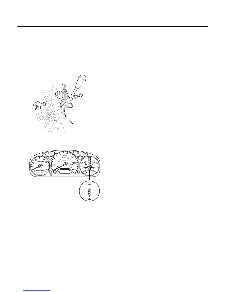
Shift Lever Installation

8 x 1.25 mm
22 N·m (2.2 kgf·m,
16 lbf·ft)

SRS components are located in this area. Review the
SRS component locations (see page 23-18), and the
precautions and procedures (see page 23-21) in the SRS
before performing repairs or service.

1. Install the shift lever assembly on the steering

column.

2. Turn the ignition switch ON (II), and verify that

the N position indicator comes on.

3. Install the shift cable end to the shift lever. If

necessary, adjust the shift cable (see step 5 on
page 14-162).

03/07/29 09:33:55 61S0X050_140_0161

01

S0X4AA0E10411412282MFAT00

14-159

Shift Lever Disassembly/Reassembly

SHIFT LOCK
SOLENOID

SHIFT LEVER ASSEMBLY

8 x 1.25 mm
12 N·m (1.2 kgf·m,
8.7 lbf·ft)

WASHER

CONTROL BRACKET

CONTROL BRACKET
COLLAR

SELECT LINK

SELF-LOCKING NUT
6 x 1.0 mm
9.8 N·m (1.0 kgf·m,
7.2 lbf·ft)

SHIFT CABLE

SHIFT LEVER BUSHING

PIVOT WASHER

4 mm SCREW
3 N·m (0.3 kgf·m, 2 lbf·ft)

DETENT SPRING

SHIFT LOCK EXTENSION

SHIFT LOCK CUSHION

SHIFT LOCK SOLENOID PLUNGER

PLUNGER SPRING

4 mm SCREW
3 N·m (0.3 kgf·m, 2 lbf·ft)

WASHER

SHIFT LEVER KNOB
9 N·m (0.9 kgf·m, 7 lbf·ft)

Apply silicone grease to these parts:

• Sliding surfaces on the detent plate.
• Sliding area on shift lever and control bracket.
• Movable parts of the shift lock mechanism.
• Select link and shift lever contacting area.
• Select link and control bracket contacting area.
• One side of washer opposite of the self-locking nut.
• Pivot washer.
• Shift lever bushing.

03/07/29 09:33:56 61S0X050_140_0162

01

02

03

S0X4AA0E10411412281KBAT00

14-160

Automatic Transmission

Shift Cable Replacement

D

B

A

E

C

F

B

A

6 x 1.0 mm
9.8 N·m (1.0 kgf·m, 7.2 lbf·ft)

A

B

C

D

E

SRS components are located in this area. Review the
SRS component locations (see page 23-18), and the
precautions and procedures (see page 23-21) in the SRS
before performing repairs or service.

1. Raise the front of the vehicle, and make sure it is

securely supported.

2. Set the parking brake, and block the rear wheels

securely.

3. Remove the steering column covers (see page 17-

25).

4. Shift the transmission into the N position.

5. Remove the nut (A) securing the shift cable end (B),

then separate the shift cable (C) from the shift lever
assembly (D).

6. Rotate the socket holder (E) on the shift cable

counterclockwise a quarter turn, then slide the
holder to remove the shift cable from the shift cable
bracket (F).

7. Remove the shift cable guide bracket (A) and

grommet (B).

8. Remove the bolts securing the shift cable holder (A),

then remove the shift cable cover (B).

NOTE: To prevent damage to the control lever joint,
remove the bolts securing the shift cable holder
before removing the bolts securing the shift cable
cover.

9. Remove the lock bolt (C) securing the control lever

(D), then remove the shift cable (E) with the control
lever.

03/07/29 09:33:56 61S0X050_140_0163

04

14-161

A

B

C

F

E

G

D
6 x 1.0 mm
14 N·m (1.4 kgf·m,
10 lbf·ft)

8 x 1.25 mm
22 N·m (2.2 kgf·m,
16 lbf·ft)

6 x 1.0 mm
9.8 N·m (1.0 kgf·m,
7.2 lbf·ft)

10. Insert the new shift cable through the grommet

hole, then install the shift cable guide bracket.

11. Verify that the transmission is in the N position on

the control shaft.

12. Install the control lever (A) with the shift cable (B)

on the control shaft (C). Do not bend the shift cable
excessively.

13. Install the lock bolt (D) with a new lock washer (E),

then bend the lock washer tab against the bolt head.

14. Install the shift cable cover (F), then install the shift

cable holder (G) on the shift cable cover.

NOTE: To prevent damage to the control lever joint,
be sure to install the shift cable holder after
installing the shift cable cover to the torque
converter housing.

15. Turn the ignition switch ON (II), and verify that the

N position indicator comes on.

16. Install the shift cable end to the shift cable. If

necessary, adjust the shift cable (see step 5 on
page 14-162).

03/07/29 09:33:57 61S0X050_140_0164


Content   ..  189  190  191  192   ..