Honda Odyssey 2004. Manual - part 186


  Index      Honda     Honda Odyssey 2004 - service repair manual 2004 year


Search            


Content   ..  184  185  186  187   ..


Honda Odyssey 2004. Manual - part 186


01

02

03

S0X4AA0E10410400000KAAT00

Special Tools Required

14-138

Automatic Transmission

Transmission Removal

A
49 N·m (5.0 kgf·m,
36 lbf·ft)

B

B

A

C

B

E

F

D

A

A

C

• Engine support hanger 07XAA-001030A
• Engine hanger balance bar VSB02C000019
• Subframe adapter EQS07AODSY0

(Available through the Honda Tool and Equipment
Program, 888-424-6857)

1. Before disconnecting the battery, make sure you

have the anti-theft code for the radio, then write
down the frequencies for the radio’s preset stations.

2. Remove the bolt securing the lower portion of the

windshield washer reservoir opening. Remove the
support rod, then fix the hood in a vertical position
using the support rod.

3. Remove the intake air duct, resonator cover, and air

cleaner housing assembly.

4. Disconnect the battery negative terminal, then

remove the positive terminal.

5. Remove the battery hold-down bracket, then

remove the battery and battery tray.

6. Remove the battery cable clamps, connector, and

relay bracket from the battery base.

7. Remove the battery base.

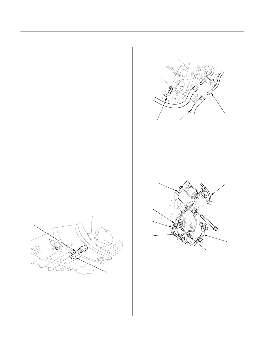
8. Raise the vehicle, and make sure it is securely

supported. Remove the drain plug (A), and drain
the automatic transmission fluid (ATF). Reinstall
the drain plug with a new sealing washer (B).

9. Remove the ATF cooler hose (A) from the clamp (B)

on the starter.

10. Remove the ATF cooler hoses (A) from the ATF

cooler lines (C). Turn the ends of the ATF cooler
hoses up to prevent ATF flowing out, then plug the
ATF cooler hoses and lines.

NOTE: Check for any signs of leakage at the hose
joints.

11. Remove the starter cables (A) from the starter (B)

and clamp bracket (C), then remove the starter.

12. Remove the transmission ground terminal (D).

13. Disconnect the shift solenoid valve B connector (E),

and C connector (F), then remove the harness
clamp from the clamp bracket.

03/07/29 09:32:42 61S0X050_140_0141

04

05

06

07

14-139

C

B

A

D

A

B

C

A

B

C

D

A

C

B

14. Disconnect the connectors from the 3rd clutch

pressure switch (A), mainshaft speed sensor (B),
and A/T clutch pressure control solenoid valves A
and B (C), then remove the harness clamps from
the clamp brackets.

15. Disconnect the connector from the torque

converter clutch solenoid valve/shift solenoid valve
A (A), then remove the connector from harness
cover (B).

16. Remove the bolt securing connector bracket (C).

17. Remove the bolt securing the harness cover, then

push the harness cover rearward to remove it from
the transmission hanger (D).

18. Disconnect the connectors from the countershaft

speed sensor (A), and 2nd clutch pressure switch
(B).

19. Remove the A/T gear position switch connector (C)

from the connector bracket (D), then disconnect it.

20. Remove the nut (A) from the front mount, and

disconnect the vacuum tube (B) at the joint (C).

(cont’d)

03/07/29 09:32:43 61S0X050_140_0142

08

09

*02

11

14-140

Automatic Transmission

Transmission Removal (cont’d)

A
(07XAA-001030A)

B
(VSB02C000019)

D

E

C

F

G

21. Remove the transmission housing mounting bolts.

22. Remove the engine covers.

23. Lift and support the engine with engine support

hanger (A) and engine balance bar (B). Attatch the
front arm (C) to the front cylinder head with a
spacer (D) and the 10 x 1.25 mm bolt (E). Attatch the
rear arm (F) the rear cylinder head with the
8 x 1.25 mm bolt (G).

24. Remove the splash shield.

03/07/29 09:32:44 61S0X050_140_0143

12

13

14

15

14-141

E

D

A

B

C

C

A

B

A

B

D

F

H

G

E

C

A

B

D

C

E

B

A

C

25. Remove the oxygen sensor connectors (A) from

their connector brackets (B), and remove the
harnesses from the clamps (C).

26. Remove the exhaust pipe A (D) and three way

catalytic converter (E).

27. Remove the spring pins (A) and castle nuts (B), and

separate the lower arms (C) from the knuckles (D)

28. Put a 6 mm Allen-type wrench (E) in the top of the

ball joint pin (F), and remove the nut (G), then
separate the stabilizer link (H).

29. Remove the bolts securing the shift cable holder (A),

then remove the shift cable cover (B).

NOTE: To prevent damage to the control lever (C),
remove the bolts securing the holder before
removing the bolts securing the cover.

30. Remove the lock bolt (D) securing the control lever,

then remove the shift cable (E) with the control
lever. Do not bend the shift cable excessively.

31. Install a 6 x 1.0 x 14 mm bolt (A) and nut (B) on the

shift cable cover (C), then reinstall the shift cable
cover to the torque converter housing.
If you don’t do this, the bolt head of the cable cover
may prevent you from removing the torque
converter during transmission removal.

(cont’d)

03/07/29 09:32:46 61S0X050_140_0144

(see page 18-11).


Content   ..  184  185  186  187   ..