Honda Odyssey 2004. Manual - part 110
−
−
−
−
−
−
*08
*05
YES
NO
YES
NO
YES
NO
11-138
PGM-FI System
DTC Troubleshooting (cont’d)
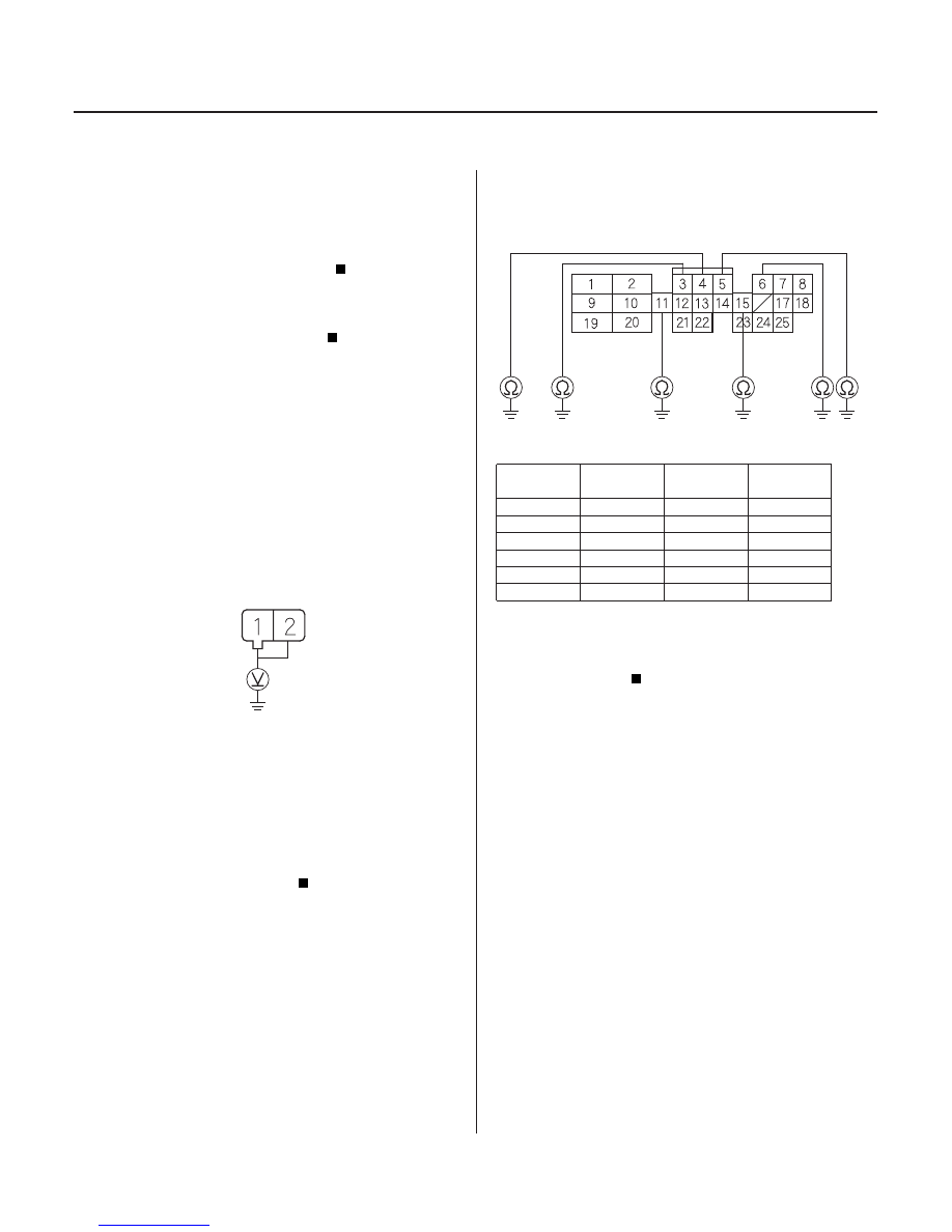
INJECTOR 2P CONNECTOR
IGP (YEL/BLK)
(’99-00 models: IGP (YEL/BLK))
PCM CONNECTOR B (25P)
INJ4 (YEL)
INJ2 (RED)
INJ6
(WHT/
BLU)
INJ3
(BLU)
INJ1
(BRN)
INJ5
(BLK/
RED)
42. Determine which cylinder had the misfire.
Replace the faulty injector.
Substitute a known-good PCM and recheck
(see page 11-5). If the symptom/indication goes
away, replace the original PCM.
43. Turn the ignition switch OFF.
44. Disconnect the injector 2P connector from the
problem cylinder.
45. Turn the ignition switch ON (II).
46. Measure voltage between injector 2P connector
ground.
Go to step 47.
Repair open in the wire between the injector
and the PGM-FI main relay.
47. Turn the ignition switch OFF.
48. Check for continuity between body ground and the
PCM connector terminal (see table).
PROBLEM
CYLINDER
DTC
PCM
TERMINAL
WIRE
COLOR
No. 1
P0301
B11
BRN
No. 2
P0302
B5
RED
No. 3
P0303
B15
BLU
No. 4
P0304
B4
YEL
No. 5
P0305
B3
BLK/RED
No. 6
P0306
B6
WHT/BLU
Repair short in the wire between the PCM
and the injector.
Go to step 49.
Wire side of female terminals
Wire side of female terminals
Does the misf ir e occur in the other cylinder wher e
the injector was exchanged?
Is ther e batter y voltage?
Is ther e continuity?
03/07/29 09:21:27 61S0X050_110_0138
terminal No. 1 (No. 2 on ’99 - 00 models) and body
’