Honda Odyssey 2004. Manual - part 102
−
−
−
−
−
−
−
−
−
−
−
−
−
−
S0X4A00K77100090116FAAT00
*01
S0X4AZ6K77100090117FAAT00
DTC P0116:
DTC P0117
’99-00, ’02-04 Models:
YES
NO
YES
NO
YES
NO
YES
NO
YES
NO
11-106
11-106
PGM-FI System
DTC Troubleshooting (cont’d)
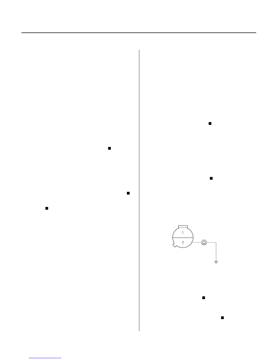
ECT SENSOR 2P CONNECTOR
ECT
(RED/WHT)
ECT Sensor Range/Performance
Problem
ECT
Sensor Circuit Low Voltage
NOTE: If DTC P0117 and/or P0118 are stored at the
same time as DTC P0116, troubleshoot those DTCs first,
then recheck for DTC P0116.
1. Start the engine. Hold the engine at 3,000 rpm with
no load (in Park or neutral) until the radiator fan
comes on, then let it idle.
2. Check the ECT with the scan tool or the HDS.
Go to step 3.
Check the thermostat and the cooling system.
If they are OK, replace the ECT sensor.
3. Test drive the vehicle with the scan tool connected,
and monitor the thermostat and cooling system for
abnormal fluctuations in temperature readings.
Check the thermostat and cooling system.
Intermittent failure, system is OK at this
time.
1. Turn the ignition switch ON (II).
2. Check the ECT with the scan tool or the HDS.
Go to step 3.
Intermittent failure, system is OK at this time.
Check for poor connections or loose terminals at
the ECT sensor and the PCM.
3. Disconnect the ECT sensor 2P connector.
4. Check the ECT with the scan tool or the HDS.
Go to step 5.
Replace the ECT sensor.
5. Turn the ignition switch OFF.
6. Disconnect PCM connector C (31P).
7. Check the continuity between ECT sensor 2P
connector terminal No. 2 and body ground.
Repair short in the wire between the PCM
(C26) and the ECT sensor.
Substitute a known-good PCM and recheck
(see page 11-5). If normal ECT readings are
indicated, replace the original PCM.
Wire side of female terminals
Is 17 6
200°F ( 80
93°C) or 0.4
0.7 V
indicated?
Ar e ther e any f luctuations in the temper atur e
r eadings?
Is 302°F ( 150°C) or higher ( or H-Limit in the HDS),
or 0 V indicated?
Is 302°F ( 150°C) or higher ( or H-Limit in the HDS),
or 0 V indicated?
Is ther e continuity?
03/07/29 09:21:11 61S0X050_110_0106