Honda Odyssey 2004. Manual - part 65


  Index      Honda     Honda Odyssey 2004 - service repair manual 2004 year


Search            


Content   ..  63  64  65  66   ..


Honda Odyssey 2004. Manual - part 65


*01

S0X4A00A32200043502LAAT00
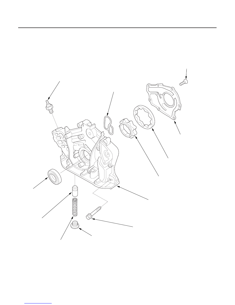
Exploded View

8-8

Engine Lubrication

Oil Pump Overhaul

ENGINE OIL PRESSURE SWITCH
18 N·m (1.8 kgf·m, 13 lbf·ft)

OIL SEAL

O-RING

6 x 1.0 mm
6 N·m (0.6 kgf·m, 4 lbf·ft)

PUMP COVER

OUTER ROTOR

INNER ROTOR

PUMP HOUSING

6 x 1.0 mm
12 N·m (1.2 kgf·m, 8.7 lbf·ft)

SEALING BOLT
39 N·m (4.0 kgf·m, 29 lbf·ft)

SPRING

RELIEF VALVE

1/8 in. BSPT (British standard pipe taper)
28 threads/inch. Use the
proper liquid sealant.

Replace.

Replace.

Apply liquid gasket
to the mating surface of
the cylinder block
when installing.

Valve must slide freely
in the housing bore.
Replace if it is scored.

03/07/29 09:13:46 61S0X050_080_0008

*02

*03

*04

Special Tools Required

Inner Rotor-to-Outer Rotor Radial Clearance
Standard (New): 0.04

0.16 mm

(0.002

0.006 in.)

Service Limit:

0.20 mm (0.008 in.)

Housing-to-Rotor Axial Clearance
Standard (New): 0.02

0.07 mm

(0.001

0.003 in.)

Service Limit:

0.12 mm (0.005 in.)

Removal

Inspection

8-9

B

A

A

B

B

A

Oil seal driver 64 070AD-RCA0100

1. Drain the engine oil.

2. Turn the crankshaft so that the No. 1 piston is at top

dead center (see page 6-20).

3. Remove the timing belt (see page 6-20).

4. Remove the crankshaft position (CKP) sensor, then

remove the timing belt drive pulley (see step 4 on
page 7-12).

5. Attach the chain hoist to the engine hanger on the

power steering (P/S) pump bracket (see step 48 on
page 5-10).

6. Remove the jack from under the oil pan.

7. Remove the VTEC solenoid valve and oil filter

assembly (see page 6-10).

8. Remove the oil pan (see page 7-11).

9. Remove the oil screen (A).

10. Remove the mounting bolts and the oil pump

assembly (B).

1. Remove the screws from the pump housing, then

separate the housing and cover.

2. Check the inner-to-outer rotor radial clearance

between the inner rotor (A) and outer rotor (B). If
the inner-to-outer rotor clearance exceeds the
service limit, replace the oil pump assembly.

3. Check the housing-to-rotor axial clearance between

the rotors (A) and pump housing (B). If the housing-
to-rotor axial clearance exceeds the service limit,
replace the oil pump assembly.

(cont’d)

03/07/29 09:13:47 61S0X050_080_0009

*05

*06

Housing-to-Outer Rotor Radial Clearance
Standard (New): 0.14

0.19 mm

(0.006

0.007 in.)

Service Limit:

0.20 mm (0.008 in.)

Installation

8-10

Engine Lubrication

Oil Pump Overhaul (cont’d)

A

B

070AD-RCA0100

4. Check the housing-to-outer rotor radial clearance

between the outer rotor (A) and pump housing (B).
If the housing-to-outer rotor radial clearance
exceeds the service limit, replace the oil pump
assembly.

5. Inspect both rotors and pump housing for scoring

or other damage. Replace parts if necessary.

6. Apply liquid thread lock to the pump housing

screws, then install the oil pump cover. Torque the
bolts to 12 N·m (1.2 kgf·m, 8.7 lbf·ft).

7. Check that the oil pump turns freely.

1. Remove the old oil seal from the oil pump.

2. Gently tap in the new oil seal until the special tool

bottoms on the pump.

3. Remove old liquid gasket from the oil pump mating

surfaces, bolts and bolt holes.

4. Clean and dry the oil pump mating surfaces.

03/07/29 09:13:48 61S0X050_080_0010

*07

*08

*09

8-11

6 x 1.0 mm
12 N·m (1.2 kgf·m,
8.7 lbf·ft)

6 x 1.0 mm
12 N·m (1.2 kgf·m,

8.7 lbf·ft)

A

B

C

D

B

Apply liquid gasket
along the broken line.

5. Install the oil pump (A).

–1 Apply liquid gasket, P/N 08718-0001 or 08718-

0003, evenly to the block mating surface of the
oil pump and to the inner threads of the bolt
holes.

NOTE: Do not install the parts if 4 minutes or
more have elapsed since applying liquid
gasket. Instead, reapply liquid gasket after
removing old residue.

–2 Grease the lip of the oil seal, and apply oil to

the new O-rings (B).

–3 Install the dowel pins (C), then align the inner

rotor with the crankshaft and install the oil
pump.

–4 Clean the excess grease off the crankshaft, and

check the seal for distortion.

6. Install the oil screen (D).

7. Clean and dry the oil pan mating surfaces.

8. Apply liquid gasket, part No. 08718-0001 or 08718-

0003, evenly to the oil pan mating surface of the
block and to the inner threads of the bolt holes.

NOTE: Do not install the parts if 4 minutes or more
have elapsed since applying liquid gasket. Instead,
reapply liquid gasket after removing the old
residue.

9. Install the oil pan on the cylinder block.

10. Tighten the bolts in two or three steps. In the final

step, tighten all bolts, in sequence, to 12 N·m
(1.2 kgf·m, 8.7 lbf·ft).

NOTE: After assembly, wait at least 30 minuites
before filling the engine with oil.

11. Install the VTEC solenoid valve and oil filter

assembly (see page 6-10).

12. Install the timing belt drive pulley, then install the

CKP sensor (see step 32 on page 7-27).

13. Install the idler pulley.

14. Install the timing belt (see page 6-23).

15. Remove the chain hoist.

03/07/29 09:13:49 61S0X050_080_0011


Content   ..  63  64  65  66   ..