Honda Civic. Manual - part 437


  Index      Honda     Honda Civic - service repair manual 2006-2009 year


Search            


Content   ..  435  436  437  438   ..


Honda Civic. Manual - part 437


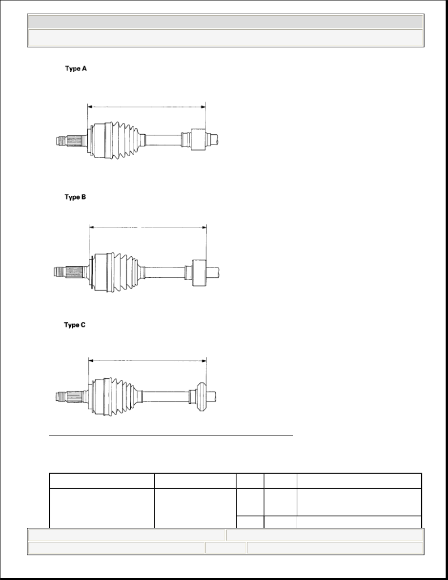
Fig. 23: Identifying Dynamic Damper Dimension 
Courtesy of AMERICAN HONDA MOTOR CO., INC. 

DYNAMIC DAMPER POSITION 

Model

Factory


Type

Measurement

Suzuka Factory

Right

Type 
A

292.5-297.5 mm (11.70-
11.90 in.)


2008 Honda Civic GX 

2006-08 DRIVELINE/AXLES Driveline/Axle - Civic (All Except Hybrid)


5. Install the dynamic damper band (see step 10 ).  
6. Install the inboard joint (see INBOARD JOINT SIDE ).  

DRIVESHAFT REASSEMBLY 

EXPLODED VIEW 

5-speed M/T Model 
(Except Si)

Left

Type 
A

292.5-297.5 mm (11.70-
11.90 in.)

Except Suzuka 
Factory

Right

Type 
A

293.0-297.0 mm (11.72-
11.88 in)

Left

Type 
A

293.0-297.0 mm (11.72-
11.88 in.)

6-speed M/T Model 
(Si)


Right

Type 
B

284.0-288.0 mm (11.18-
11.34 in.)

Left

Type 
B

284.0-288.0 mm (11.18-
11.34 in.)

A/T Model

Suzuka Factory

Right

Type 
A

558.0-563.0 mm (22.32-
22.52 in.)

Left

Type 
C

274.5-279.5 mm (10.98-
11.18 in.)

Except Suzuka 
Factory

Right

Type 
A

558.5-562.5 mm (22.34-
22.50 in.)

Left

Type 
C

275.0-279.0 mm (11.00-
11.18 in.)


2008 Honda Civic GX 

2006-08 DRIVELINE/AXLES Driveline/Axle - Civic (All Except Hybrid)


Fig. 24: Exploded View Of Driveshaft Components 
Courtesy of AMERICAN HONDA MOTOR CO., INC. 

Special Tools Required  


Boot band tool, KD-3191 or equivalent commercially available  


Boot band pliers, Kent-Moore J-35910 or equivalent commercially available  

NOTE:

Refer to the exploded view, as needed, during this 


2008 Honda Civic GX 

2006-08 DRIVELINE/AXLES Driveline/Axle - Civic (All Except Hybrid)


INBOARD JOINT SIDE 

1. Wrap the splines with vinyl tape (A) to prevent damaging to the inboard boot. 

Fig. 25: Identifying Splines With Vinyl Tape 
Courtesy of AMERICAN HONDA MOTOR CO., INC. 

2. Install the inboard boot onto the driveshaft, then remove the vinyl tape. Be 

careful not to damage the inboard boot.  

3. Install the spider (A) onto the driveshaft by aligning the marks (B) you made 

on the spider and the end of the driveshaft. 

Fig. 26: Aligning Marks On Spider Of Driveshaft 
Courtesy of AMERICAN HONDA MOTOR CO., INC. 

4. Fit the circlip (C) into the driveshaft groove. Always rotate the circlip in its 

procedure. See Fig. 24.


2008 Honda Civic GX 

2006-08 DRIVELINE/AXLES Driveline/Axle - Civic (All Except Hybrid)


Content   ..  435  436  437  438   ..