Great Wall Florid. Manual - part 7
GWFLORID Maintenance Manual
26
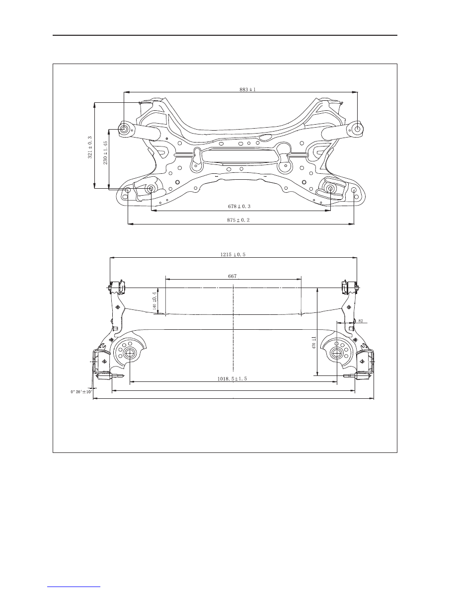
Subframe
Unit: mm
1195
±
1.5 ( Distance between the center points of both shaft's end surfaces )
1381
±
0.5 ( Distance between points P and Q )
|
|
|
GWFLORID Maintenance Manual 26 Subframe Unit: mm 1195 ± 1.5 ( Distance between the center points of both shaft's end surfaces ) 1381 ± 0.5 ( Distance between points P and Q ) |