Geely Emgrand X7. Manual part - 637


  Главная      Geely     Geely Emgrand X7 - Manual


поиск по сайту            


содержание   ..   634  635  636  637  638  ..


Geely Emgrand X7. Manual part - 637
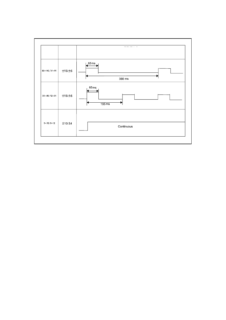


11.13.2.2 Sound level of alarm prompt tone 

NL11-3010b


Detection 

distance 

(cm/in) 

Distance 

error 

(cm/in) 


Alarmprompt tone   
(Time error±10%) 

2547


11.13.2.3 Sensor area 

Sensor coverage map 

NL11-3011b


Test conditions 

– Use 

Φ750mm PVC pipe to cover the complete vehicle. 

– 

Testing temperature 25℃ 

– 

Testing wetness 45-75 % RH 

Vertical 
distance 

Horizontal 

distance 

2548

Rear three-probe overall coverage diagram 

NL11-8002b

6

57.

9

0.

0

0.

1

0.

2

0.

5

0.

4

0.

3

0.

9

1.

0

0.

8

0.

7

0.

6

1.

1

1.

2

1.

3

1.

4

0.

0

0

.3

7.

0

6.

0

2.

04

.

05

.00

.8

5.

04

.03

.

02

.

01

.0

0.

8

0

.6

0.

7

8.

0

7.

0

6.

0

5.

0

4.

0

3.

0

2.

0

1.

0

0.

0

1.

0

2.

0

3.

0

4.

0

5

.0

6.

0

8.

07

.0

0.

1

:M

0.

0

0.

1

0.

2

0.

5

0.

4

0.

3

0.

9

1.

0

0.

8

0.

7

0.

6

1.

1

1.

2

1.

3

1.

4

M

2

.

1°

1851.9

869.0


Front two-probe overall coverage diagram 

NL11-8003b

M

0.

0

0.

1

0.

2

0.

5

0.

4

0.

3

0.

9

1.

0

0.

8

0.

7

0.

6

1.

1

1.

2

1.

3

1.

4

2.

03

.0

0.

00

.6

0.

7

0.

5

0.

4

0.

8

0.

4

0.

5

2.

01

.0

0.

3

7.

06

.0

8.

0

8.

0

7.

0

6.

0

5.

0

4.

0

3.

0

2.

0

1.

0

0.

0

1.

0

2.

0

3.

0

4.

0

5.

0

6.

0

8.

07

.0

0.

1

0.

0

0.

1

0.

2

0.

5

0.

4

0.

3

0.

9

1.

0

0.

8

0.

7

0.

6

1.

1

1.

2

1.

3

1.

4

30. 3°

303. 6

0TNP0TNPA

0TNP0TNPA

42

1.

1

1239. 8


Full load 

ground line

Full load 

ground line 

2549


11.13.3 System operating principle 

11.13.3.1 Control unit function of parking motor 

NO Functional 

planning NO Functional 

planning 

1 

Generate the TX (48KHz square wave) 
signal driving the sensor and USART 
signal (bit rate 2400bps) of the 
instrument panel. 

6 

Detect the driver's reversing signal 
(0V low. 

The level is valid; and if invalid, the 
level is +12V. 

2 

Receive RX (obstacle echo) signal from 
the sensor. 

7 

Detect the vehicle transmitted back 
through wheel speed sensor. 

Speed signal 

3 

The RX signal from the sensor is 
converted as digital pulse signal after 
being filtered and demodulated by the 
module. 

8 

Sensor Malfunction Diagnosis 

4 

The module detection calculates the 
distance of the obstacle and the 
corresponding frequency alarming digital 
signal to the dashboard within specified 
range. 

9 

Detect the key signal input by the 
driver. 

(reserve+12V HF is effective) 

5 

Provide the stable driving voltage to the 
sensor. 

10 

Detect the driver's reversing signal 
(+12V. 

High level is valid.) 

11.13.3.2 Parking motor work logic 

Work mode 

Dashboard input signal acquisition state 

Enabling state of the front and 
rear sensors 

Reversing mode 

R speed effective 

All the sensors work. 

Parking mode 

Stop mode (Gear P or hand brake signal) 

All the sensors do not work. 

Running speed ≤ 10km/h 

Left front/ right front sensor 
working 

Forward mode 

Running speed > 10km/h 

All the sensors do not work. 

Mute button 
reserved 

Close buzzer beeps. For non-self-locking key, operate once, and switch the 
silent alarm state. 

2550


содержание   ..   634  635  636  637  638  ..