Geely Emgrand X7. Manual part - 99


  Главная      Geely     Geely Emgrand X7 - Manual


поиск по сайту            


содержание   ..    92  93  94  95  96  97  98  99   100  .. 


Geely Emgrand X7. Manual part - 99
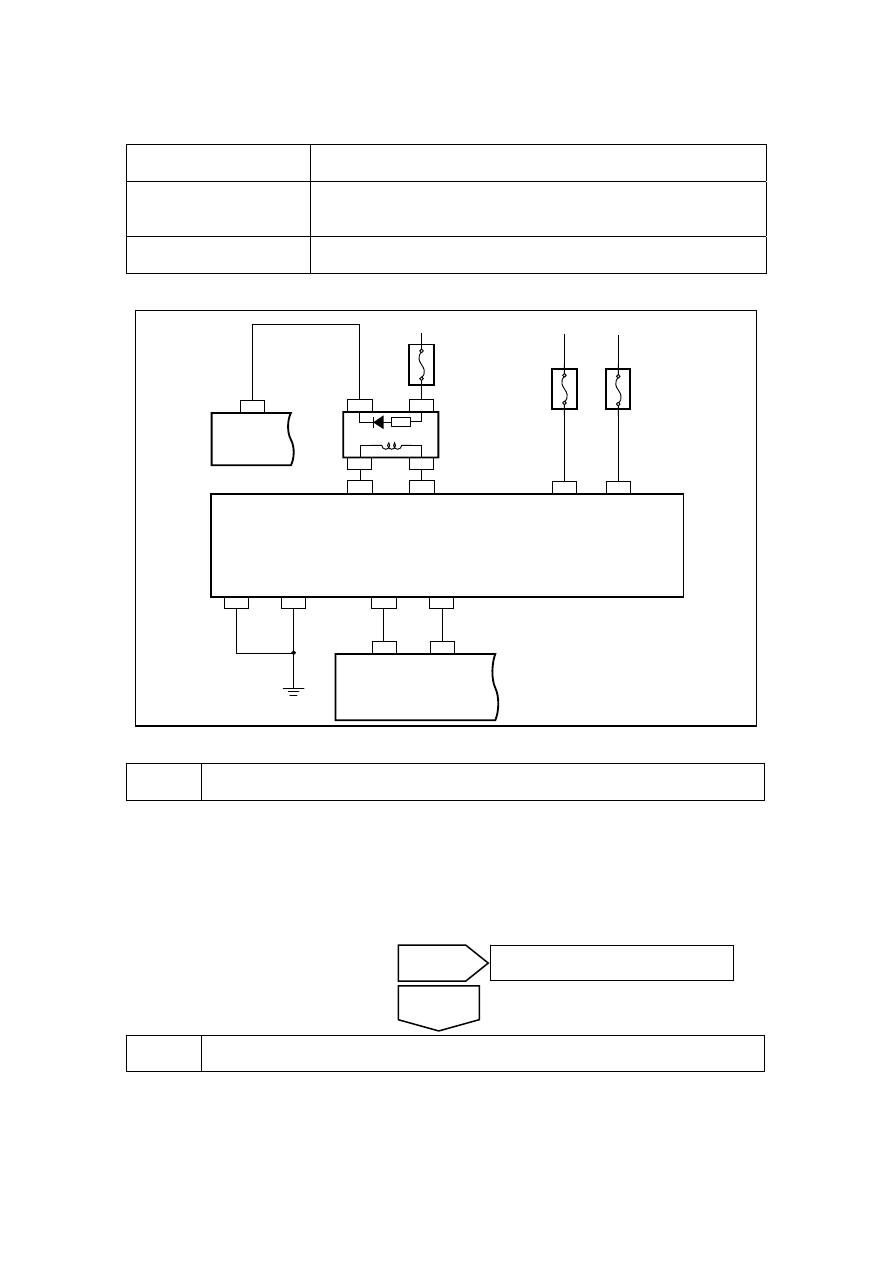


2.5.7.12 DTC 9000 B061 

Fault diagnosis code Descriptions 

9000 

Antenna Failure (Only When Read Anti-theft Transponder, Not 
Received During Continuous Test). 

B061 

Key is unable to be verified or the communication is disturbed. 

Circuit diagram: 

NL02-2300b

3 IP25

2 IP24

5 IP24

8 IP24

1 IP24

4 IP24

46 EN01

75 EN01

芯片防盗模块

ECM

IMMOREQ

KW2000

GND

GND

IG2

VBATT

R-LINE

W-LINE

5 IP43

IP25

1

2 IP43

IP25

2

IP43

4

IP43

3

10A

IF

35

10A

IF0

2

IP+B

IG2

15A

IF

06

ACC

IP49

2

BCM

KEY LIGHT

防盗天线


Diagnostic Steps: 

1 

Measure VVT solenoid valve resistance. 

(a)  Rotated ignition switch to "OFF" position . 

(b)  Disconnect electronic Anti-theft coil harness connector IP25. 

(c)  Disconnect engine anti-theft module wire harness connector IP24. 

(d)  Inspect EAS Coil and engine anti-theft module harness connector. 

onfirm whether the harness connector is well inserted and the connector harness breaks off. 


2 Inspect 

Anti-theft 

Coil 


Yes 

Repair or reconnect the wire harness 
connector. 

No 

Immobilizer 

antenna 

Chip anti-theft 

module 

395

(a)  Rotated ignition switch to "OFF" 

position . 

(b) Disconnect electronic Anti-theft 

coil harness connector IP25. 

(c) Measure  resistance  between 

terminal 1 and 2. 

Standard Resistance Value: 10~20 Ω

(d) Measure  resistance  between 

terminal 2 and 3. 

Standard Resistance: 10 kΩ or 
higher 

Confirm if the resistance conforms to 
standard value. 

NL11-2301b

1

2

3

电子防盗线圈

1

2

3


3 

Replace engine anti-theft module. 

Replace engine anti-theft module and refer to 2.5.8.2 "Replacement of Engine Anti-Theft System 
Control Module". 

(b)  Refer to 2.5.7.9 “Replacement of programming after anti-theft module” to match the engine 

anti-theft system. 

(c)  Use the Fault Diagnosis Tester to Clear DTC code. 

Confirm the completion of repair. 


4 

The system is normal. 

Next 

No 

Replace electronic Anti-theft coil. 

Yes 

Eclectic anti-theft coil 

396

2.5.7.13 DTC B040 B402 B403 

Fault diagnosis code Descriptions 

B040 

W line error . no response from electric injector 

B402 

W line short to the ground 

B403 

W line short to the Power Supply . 

Circuit diagram: 

NL02-2300b

3 IP25

2 IP24

5 IP24

8 IP24

1 IP24

4 IP24

46 EN01

75 EN01

芯片防盗模块

ECM

IMMOREQ

KW2000

GND

GND

IG2

VBATT

R-LINE

W-LINE

5 IP43

IP25

1

2 IP43

IP25

2

IP43

4

IP43

3

10A

IF

35

10A

IF0

2

IP+B

IG2

15A

IF

06

ACC

IP49

2

BCM

KEY LIGHT

防盗天线


Diagnostic Steps: 

1 

Inspect engine chip anti-theft module W line circuit. 


(a)  Rotated ignition switch to "OFF" 

position . 

(b) 

Disconnect ECM harness 
connector EM01. 

(c) Disconnect  engine  anti-theft 

module wire harness connector 
IP24. 

(d)  Inspect the circuit between the 

ECM harness connector EM01 
terminal 75 and the engine 
anti-theft module harness 
connector IP24 terminal 8. 

NL02-2189b

1

2

4

6

8

3

5

7

IP24 发动机防盗控制模块线束连接器1

Immobilizer 
antenna 

Chip anti-theft module

IP24 engine anti-theft control module 

harness connector1 

397


IP24(8)-EM01(75)  

Less than 1 Ω 

IP24 (8) and Body Ground 

10 kΩ or higher 

IP24 (8) and Body Ground 

0V 

Confirm whether according with the standard value. 


2 

Replace engine anti-theft module. 

(a)  Replace engine anti-theft module and refer to 2.5.8.2 "Replacement of Engine Anti-Theft 

System Control Module". 

(b)  Refer to 2.5.7.9 “Replacement of programming after anti-theft module” to match the engine 

anti-theft system. 

(c)  Use the Fault Diagnosis Tester to Clear DTC code. 

Confirm the completion of repair. 


3 

Inspect the ECM Power Supply and Grounding Circuits. 

(a)  Repair ECM power supply circuit. 

(b)  Check ECM grounding circuit. 


4 Replace 

ECM 

(a)  Replace ECM and refer to 2.2.8.1 "Replacement of Engine Control Module". 

(b)  Match engine anti-theft system, refer to 2.5.7.10 Compilation after replacement of ECM. 

Confirm the completion of repair. 


5 

The system is normal. 

Next 

Yes 

The system is normal. 

No 

Yes 

Repair the wire harness 

No 

398


содержание   ..    92  93  94  95  96  97  98  99   100  ..