Foton Series Light Bus. Service Manual - part 5
OPERATION AND MAINTENANCE MANUAL FOR FOTON VIEW SERIES LIGHT BUS
·56·
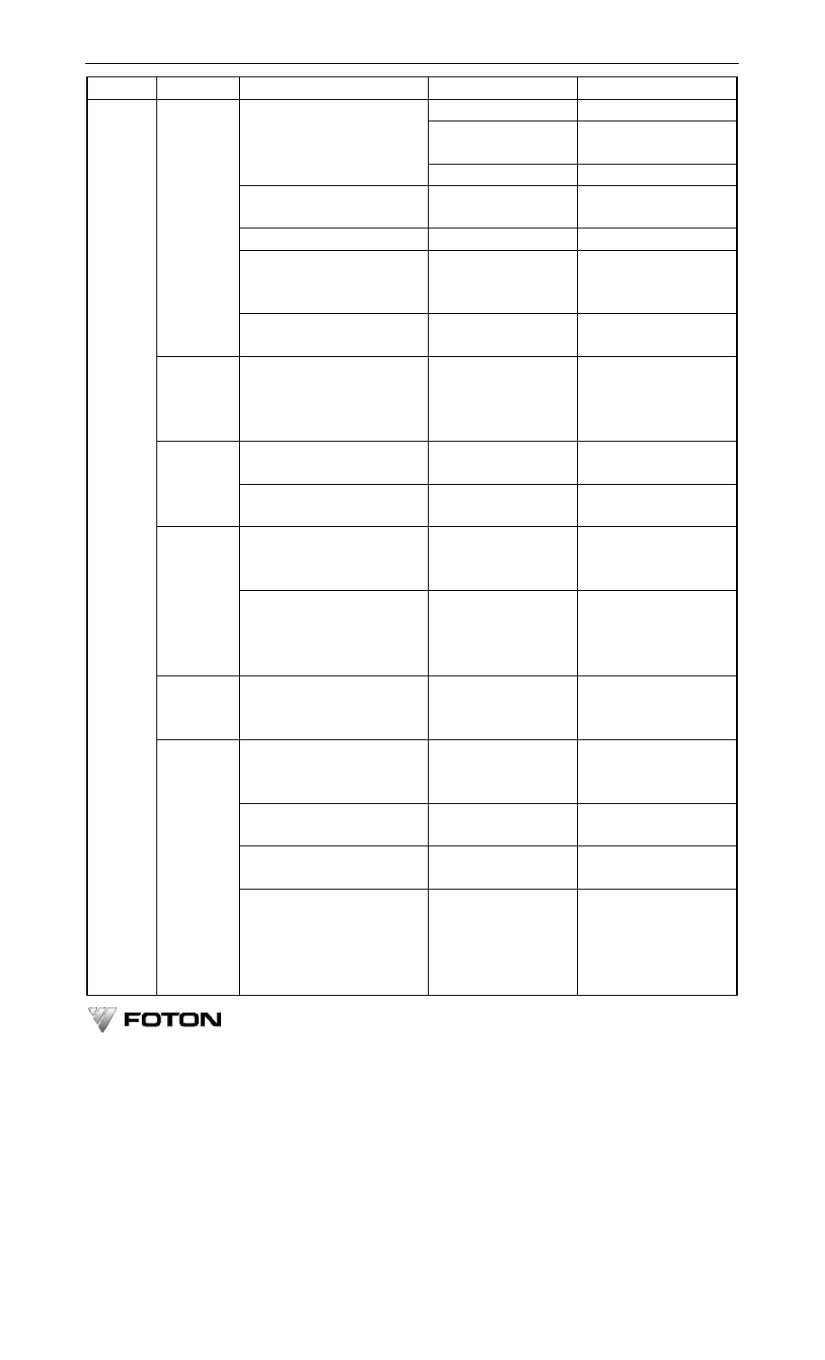
Category
Location
Check results
Faults
Additional services
Valve spring broken
Replace valve spring
Noise--camshaft bearing Remove to check camshaft
bearing
Abnormal
sound
-
valve
mechanism
Worn timing gear
Replace timing gear
Larger
crankshaft
axial
clearance
Worn crankshaft thrust
washer
Replace thrust washer
Oil leak at crankshaft oil seal
Oil seal failure
Replace oil seal
Abnormal sound-- water pump Water
pump
shaft
bearing
damaged
or
shaft broken
Remove to check water
pump, replace bearing or
water pump
Engine
Engine over heated
Radiator pipe restricted Remove to check, remove
pipe restrictions.
Clutch
Clutch failure
Clutch skipping, worn
friction
plate,
incomplete
release,
unstable engagement
Remove to check clutch,
replace friction plate or
return spring
Abnormal
sound - clutch
release bearing
Bearing damaged
Replace release bearing
Transmission
Abnormal sound or frequent
repair--transmission
Worn or broken shaft,
gear, bush
Remove
to
check
transmission
Enlarged meshing clearance or
abnormal sound-final drive’s
drive/driven gears
Worn gear face or larger
meshing clearance
Adjust meshing clearance,
check gear fitting.
Axle
abnormal
sound-differential,
final
drive,
axle
case
temperature > 60 ℃ (frequent
minor repair)
Incorrect gear meshing
or tooth broken
Remove to check final
drive and differential
Steering
gear
steering wheel free travel>10
º, stuck or heavy
Larger
meshing
clearance, worn gear,
ball groove worn to stick
Adjust steering wheel free
travel, remove to check
steering gear
Abnormal
and
free
play-propeller shaft counter
bearing
Radial play or bearing
worn to stick
Remove to check counter
bearing
Brake failure (adjustment does
not work)
Worn-out brake pad
Remove
to
check
or
replace pad / shoe
Body deformed, serious paint
peel-off
Metal crack, rust
Repair, weld and paint
manual
check
Others
tyre side wear
Front
axle
distorted,
steering knuckle kingpin
play, axle parts distorted
Perform
front
wheel
alignment,
remove
to
check or replace kingpin
or bush, correct or replace
distorted parts