Ford Galaxy / Ford S-MAX. Manual - part 919
 

  Index      Ford     Ford Galaxy / Ford S-MAX - service repair manual 2006 year


Search            


Content   ..  917  918  919  920   ..


Ford Galaxy / Ford S-MAX. Manual - part 919


TEST the system for normal operation.  

No 

Inoperative left-hand rear quarter power window - 
REPAIR circuit CPW26B (BU/BN). TEST the system 
for normal operation. 
Inoperative right-hand rear quarter power window - 
REPAIR circuit CPW28A (WH/BN). TEST the system 
for normal operation. 

PINPOINT TEST D : THE DEFROST SYSTEM IS INOPERATIVE 

TEST CONDITIONS

DETAILS/RESULTS/ACTIONS

D1: CHECK THE OPERATION OF THE HEATED REAR WINDOW

NOTE: Use a digital multimeter for all electrical measurements. 

Ignition switch in position III. 

1 

Ignition switch in position II. 

2 

Operate the heated rear window switch.  

3 

Does the heated rear window function correctly? 
Yes 

GO to D2

.  

No 

GO to D3

.  

D2: CHECK THE OPERATION OF THE HEATED WINDSHIELD

Operate the heated windshield control switch.  

1 

Does the heated windshield operate correctly? 
Yes 

VERIFY the customer concern.  

No 

GO to D6

.  

D3: CHECK THE OPERATION OF THE HEATED REAR WINDOW SWITCH LED

Operate the heated rear window switch.  

1 

Does the heated rear window switch ON LED illuminate? 
Yes 

GO to D4

.  

No 

GO to D10

.  

D4: CHECK FOR VOLTAGE TO THE HEATED REAR WINDOW GRID WIRES

Ignition switch in position 0. 

1 

Disconnect Heated Rear Window Grid Wires 
C4RD02-A. 

2 

Ignition switch in position III. 

3 

Ignition switch in position II. 

4 

Operate the heated rear window switch.  

5 

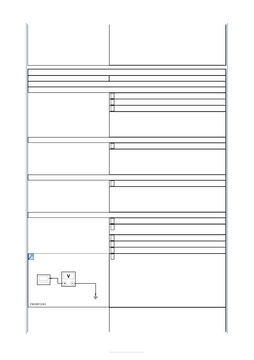
Measure the voltage between the heated rear 
window grid wire CC4RD02-A pin 1, circuit CRD06C 

(BN/YE), harness side and ground. 

6 

Is the voltage greater than 10 volts? 
Yes 

GO to D5

.  

No 


GO to D13

.  

D5: CHECK THE HEATED REAR WINDOW GRID GROUND CIRCUIT

Ignition switch in position 0. 

1 

Disconnect Heated Rear Window Grid Wires 
C4RD02-B. 

2 

Measure the resistance between the heated rear 
window C4RD02-B pin 1, circuit GD150AE 

(BK/WH), harness side and ground.  

3 

Is the resistance less than 5 ohms? 
Yes 

CARRY OUT the Heated Rear Window Grid Wire 
Component Test in this procedure. TEST the system 
for normal operation.  

No 

REPAIR circuit GD150AE (BK/WH). TEST the system 
for normal operation.  

D6: CHECK THE OPERATION OF THE HEATED WINDSHIELD SWITCH LED

Operate the heated windshield switch.  

1 

Does the heated windshield switch ON LED illuminate?  
Yes 

GO to D7

.  

No 

GO to D16

.  

D7: CHECK FOR VOLTAGE TO THE HEATED WINDSHIELD GRID WIRES

Ignition switch in position 0. 

1 

Disconnect Heated Windshield Grid Wires C2RD03 
and C2RD04-A. 

2 

Ignition switch in position III. 

3 

Ignition switch in position II. 

4 

Operate the heated windshield control switch.  

5 

Measure the voltage between the:  

heated windshield left-hand grid wire C2RD03 pin 
1, circuit CBB35A (YE/GY), harness side and 
ground.  
heated windshield right-hand grid wire C2RD04-A 
pin 1, circuit CBB34B (VT/BN), harness side and 
ground.  

6 

Is the voltage greater than 10 volts? 
Yes 

GO to D8

.  

No 

GO to D18

.  

D8: CHECK THE HEATED WINDSHIELD GRID WIRE GROUND CIRCUITS

Ignition switch in position 0. 

1 

Measure the resistance between the heated 
windshield ground circuits and ground.  

2 


Are the resistances less than 5 ohms? 
Yes 

GO to D9

.  

No 

REPAIR the heated windshield ground circuit(s). 
TEST the system for normal operation.  

D9: CHECK THE HEATED WINDSHIELD GRID WIRES

Measure the resistance between the:  

heated windshield left-hand grid wire C2RD03 pin 
1, circuit CBB35A (YE/GY), harness side and 
ground.  
heated windshield right-hand grid wire C2RD04-A 
pin 1, circuit CBB34B (VT/BN), harness side and 
ground.  

1 

Are the resistances greater than 10,000 ohms? 
Yes 

INSTALL a new windshield glass.  
REFER to: Windshield Glass (501-11 Glass, Frames 
and Mechanisms, Removal and Installation). 
TEST the system for normal operation.  

No 

VERIFY the customer concern.  

D10: CHECK THE HEATED REAR WINDOW SWITCH GROUND CIRCUIT

Ignition switch in position 0. 

1 

Disconnect Heated Rear Window Switch C2RD09-B. 

2 

Measure the resistance between the heated rear 
window switch C2RD09-B pin 4, circuit GD133BN 

(BK), harness side and ground.  

3 

Is the resistance less than 5 ohms? 
Yes 

GO to D11

.  

No 

REPAIR circuit GD133BN (BK). TEST the system for 
normal operation.  

D11: CHECK FOR CONTINUITY BETWEEN THE CENTRAL JUNCTION BOX (CJB) AND 
THE HEATED REAR WINDOW SWITCH LED

Disconnect CJB C1BP02-C. 

1 

Measure the resistance between the CJB C1BP02-C 
pin 46, circuit CRD04A (BN/GN), harness side and 

the heated rear window control switch C2RD09-B 
pin 3, circuit CRD04A (BN/GN), harness side.  

2 

Is the resistance less than 5 ohms? 


Yes 

GO to D12

.  

No 

Repair circuit CRD04A (BN/GN). TEST the system 
for normal operation.  

D12: CHECK FOR CONTINUITY BETWEEN THE CENTRAL JUNCTION BOX (CJB) AND 
THE HEATED REAR WINDOW SWITCH

Measure the resistance between the CJB C1BP02-C 
pin 7, circuit CRD09A (BU/GY), harness side and 

the heated rear window control switch C2RD09-B 
pin 6, circuit CRD09A (BU/GY), harness side.  

1 

Is the resistance less than 5 ohms? 
Yes 

CARRY OUT the CJB self-test. REFER to WDS. 
CARRY OUT the Heated Rear Window Glass Switch 
component test. REFER to the Wiring Diagrams. 

No 

Repair circuit CRD09A (BU/GY). TEST the system 
for normal operation.  

D13: CHECK FOR VOLTAGE TO THE HEATED REAR WINDOW RELAY

Ignition switch in position 0. 

1 

Disconnect Heated Rear Window Relay RA2. 

2 

Measure the voltage between the heated rear 
window relay RA2 pin 1 circuit SBB19F (BU/RD), 

harness side and ground.  

3 

Is the voltage greater than 10 volts? 
Yes 

GO to D14

.  

No 

REPAIR circuit SBB19F (BU/RD). TEST the system 
for normal operation.  

D14: CHECK FOR CONTINUITY BETWEEN THE CJB AND THE HEATED REAR WINDOW 
RELAY

Disconnect CJB C1BP02-B. 

1 

Measure the resistance between the CJB C1BP02-B 
pin 26, circuit CRD02A (BN/BU), harness side and 

the heated rear window relay RA2 pin 2, circuit 
CRD02A (BN/BU), harness side.  

2 

Is the resistance less than 5 ohms? 


Content   ..  917  918  919  920   ..