Ford Galaxy / Ford S-MAX. Manual - part 797
 

  Index      Ford     Ford Galaxy / Ford S-MAX - service repair manual 2006 year


Search            


Content   ..  795  796  797  798   ..


Ford Galaxy / Ford S-MAX. Manual - part 797


Pinpoint Tests 

NOTE: Use a digital multimeter for all electrical measurements. 

lamp. 

Liftgate latch motor. 
CJB. 

*
*

The glove compartment lamp is inoperative

Fuse(s). 
Bulb(s). 
Circuit(s). 
Glove compartment 

lamp. 

CJB. 
Battery saver relay. 

*
*
*
*

*
*

GO to Pinpoint 

Test 

E. 


*

The front footwell lamp(s) are inoperative

Fuse(s). 
Bulb(s). 
Circuit(s). 
Front footwell lamp(s). 
CJB. 
Battery saver relay. 

*
*
*
*
*
*

GO to Pinpoint 

Test 

F. 


*

The vanity mirror lamp(s) are inoperative

Fuse(s). 
Bulb(s). 
Circuit(s). 
Vanity mirror lamp(s). 
CJB. 
Battery saver relay. 

*
*
*
*
*
*

GO to Pinpoint 

Test 

G. 


*

The battery saver is inoperative/does not 
operate correctly

Circuit(s). 
Door module(s). 
Door ajar switch(es). 
CJB. 

*
*
*
*

Refer to the 

WDS. 

*

PINPOINT TEST A : THE FRONT INTERIOR LAMP IS INOPERATIVE 

TEST CONDITIONS

DETAILS/RESULTS/ACTIONS

A1: CHECK OPERATION OF THE INTERIOR LAMP

Check for operation of the interior lamp in both the 
ON and DOOR OPEN positions. 

1 

Is the interior lamp inoperative in both positions? 
Yes 

GO to A3

.  

No 

If the interior lamp is inoperative in the ON position. 

GO to A5

.  

If the interior lamp is inoperative in the DOOR OPEN 
position. 

GO to A2

.  

A2: CHECK CIRCUIT CLN27G (WH/BN) AND CIRCUIT CLN27B (WH/BN) FOR OPEN 
CIRCUIT

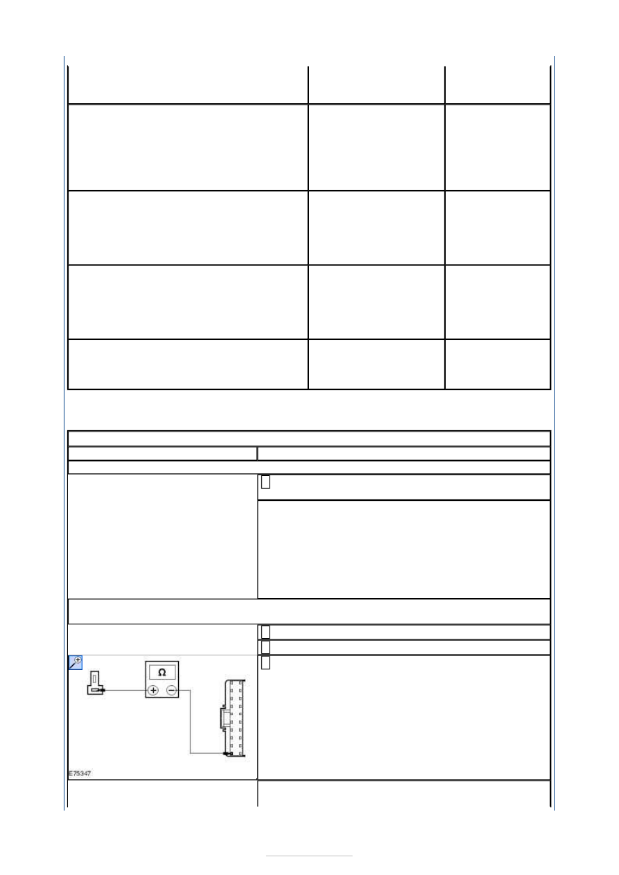
Disconnect Front Interior Lamp C9LN28-B. 

1 

Disconnect CJB C1BP02-H. 

2 

Measure the resistance between the front interior 
lamp C9LN28-B pin 1, circuit CLN27G (WH/BN), 

harness side and the CJB C1BP02-H pin 20, circuit 
CLN27B (WH/BN), harness side . 

3 

Is the resistance less than 1 ohm? 
Yes 


INSTALL a new front interior lamp. TEST the system 
for normal operation. 

No 

REPAIR the circuit(s) as necessary. TEST the system 
for normal operation. If the concern persists, 
INSTALL a new CJB. TEST the system for normal 
operation. 

A3: CHECK CIRCUIT CBP17A (BN/GN) FOR VOLTAGE

Disconnect Front Interior Lamp C9LN28-A. 

1 

Measure the voltage between the front interior lamp 
C9LN28-A pin 1, circuit CBP17A (BN/GN), harness 

side and ground. 

2 

Is the voltage greater than 10 volts? 
Yes 

INSTALL a new front interior lamp. TEST the system 
for normal operation. If the concern persists, GO to 
Pinpoint Test 

H. 


No 

GO to A4

.  

A4: CHECK FRONT INTERIOR LAMP POWER CIRCUIT FOR OPEN CIRCUIT

Disconnect CJB C1BP02-C. 

1 

Measure the resistance between the front interior 
lamp C9LN28-A pin 1, circuit CBP17A (BN/GN), 

harness side and the CJB C1BP02-C pin 67, circuit 
CBP17R (BN/GN), harness side. 

2 

Is the resistance less than 1 ohm? 
Yes 

GO to Pinpoint Test 

H. 


No 

REPAIR circuit CBP17A (BN/GN) or circuit CBP17R 
(BN/GN) as necessary . TEST the system for normal 
operation. 

A5: CHECK CIRCUIT GD138R (BK/WH) FOR GROUND

Disconnect the battery ground cable.  
REFER to: 

Battery Disconnect and Connect

 (414-01 

Battery, Mounting and Cables, General Procedures). 

1 

Disconnect Front Interior Lamp C9LN28-B. 

2 

Measure the resistance between the front interior 
lamp C9LN28-B pin 2, circuit GD138R (BK/WH), 

harness side and ground. 

3 


Is the resistance less than 1 ohm? 
Yes 

INSTALL a new front interior lamp. TEST the system 
for normal operation. 

No 

REPAIR the circuit. TEST the system for normal 
operation. 

PINPOINT TEST B : THE MIDDLE INTERIOR LAMP IS INOPERATIVE 

TEST CONDITIONS

DETAILS/RESULTS/ACTIONS

B1: CHECK OPERATION OF THE MIDDLE INTERIOR LAMP

Check for operation of the middle interior lamp in 
both the ON and DOOR OPEN positions. 

1 

Is the middle interior lamp inoperative in both positions? 
Yes 

GO to B3

.  

No 

If the middle interior lamp is inoperative in the ON 
position. 

GO to B5

.  

If the middle interior lamp is inoperative in the DOOR 
OPEN position. 

GO to B2

.  

B2: CHECK CIRCUIT CLN27H (WH/BN) AND CIRCUIT CLN27B (WH/BN) FOR OPEN 
CIRCUIT

Disconnect Middle Interior Lamp C9LN14-B. 

1 

Disconnect CJB C1BP02-H. 

2 

Measure the resistance between the middle interior 
lamp C9LN14-B pin 1, circuit CLN27H (WH/BN), 

harness side and the CJB C1BP02-H pin 20, circuit 
CLN27B (WH/BN), harness side . 

3 

Is the resistance less than 1 ohm? 
Yes 

INSTALL a new middle interior lamp. TEST the 
system for normal operation. 

No 

REPAIR the circuit(s) as necessary. TEST the system 
for normal operation. If the concern persists, 
INSTALL a new CJB. TEST the system for normal 
operation. 

B3: CHECK CIRCUIT CBP17B (BN/GN) FOR VOLTAGE

Disconnect Middle Interior Lamp C9LN14-A. 

1 

Measure the voltage between the middle interior 
lamp C9LN14-A pin 1, circuit CBP17B (BN/GN), 

harness side and ground. 

2 


Is the voltage greater than 10 volts? 
Yes 

INSTALL a new middle interior lamp. TEST the 
system for normal operation. If the concern persists, 
GO to Pinpoint Test 

H. 


No 

GO to B4

.  

B4: CHECK MIDDLE INTERIOR LAMP POWER CIRCUIT FOR OPEN CIRCUIT

Disconnect CJB C1BP02-C. 

1 

Measure the resistance between the middle interior 
lamp C9LN14-A pin 1, circuit CBP17B (BN/GN), 

harness side and the CJB C1BP02-C pin 67, circuit 
CBP17R (BN/GN), harness side. 

2 

Is the resistance less than 1 ohm? 
Yes 

GO to Pinpoint Test 

H. 


No 

REPAIR circuit CBP17B (BN/GN) or circuit CBP17R 
(BN/GN) as necessary . TEST the system for normal 
operation. 

B5: CHECK CIRCUIT GD138X (BK/WH) FOR GROUND

Disconnect the battery ground cable.  
REFER to: 

Battery Disconnect and Connect

 (414-01 

Battery, Mounting and Cables, General Procedures). 

1 

Disconnect Middle Interior Lamp C9LN14-B. 

2 

Measure the resistance between the middle interior 
lamp C9LN14-B pin 2, circuit GD138X (BK/WH), 

harness side and ground. 

3 

Is the resistance less than 1 ohm? 
Yes 

INSTALL a new middle interior lamp. TEST the 
system for normal operation. 

No 

REPAIR the circuit. TEST the system for normal 
operation. 


Content   ..  795  796  797  798   ..