Ford Galaxy / Ford S-MAX. Manual - part 714
 

  Index      Ford     Ford Galaxy / Ford S-MAX - service repair manual 2006 year


Search            


Content   ..  712  713  714  715   ..


Ford Galaxy / Ford S-MAX. Manual - part 714


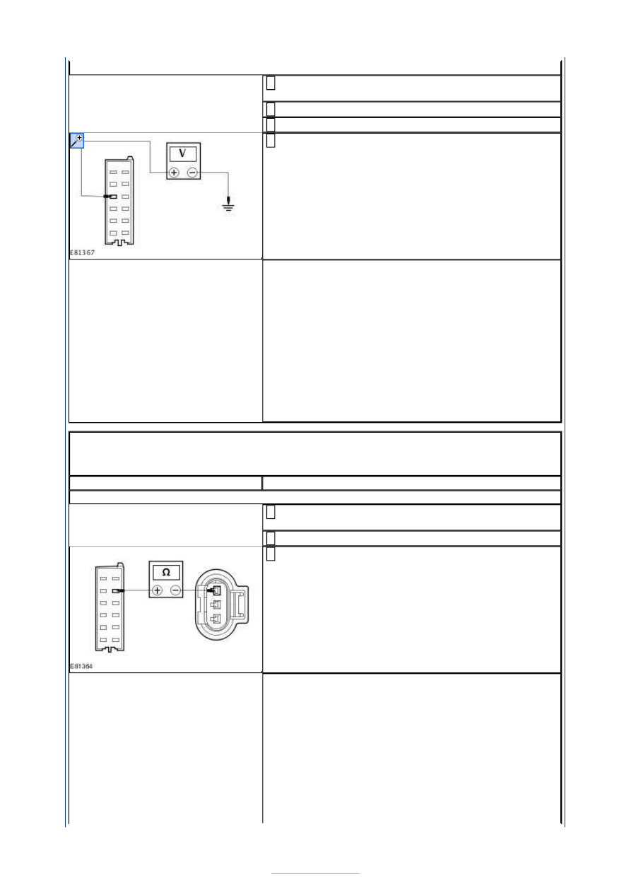
O1: CHECK CIRCUIT VMP14 (WH/OG) FOR SHORT TO POWER 

Disconnect Rear inner left parking aid sensor 
C4MP14. 

1 

Disconnect Parking aid module C4MP01C. 

2 

Ignition switch in position II. 

3 

Measure the voltage between the parking aid module 
C4MP01C pin 3, circuit VMP14A (WH/OG), harness 

side and ground. 

4 

Is a voltage present? 
Yes 

REPAIR the circuit. TEST the system for normal 
operation. 

No 

INSTALL a new rear inner left parking aid sensor.  
REFER to: 

Rear Parking Aid Sensor

 (413-13 Parking 

Aid, Removal and Installation). 
TEST the system for normal operation. If the concern 
persists, INSTALL a new parking aid module.  
REFER to: 

Parking Aid Module

 (413-13 Parking Aid, 

Removal and Installation). 
TEST the system for normal operation. 

PINPOINT TEST P : DTC B1B5096 - REAR INNER LEFT PARKING AID 
SENSOR - GROUND CIRCUIT OPEN OR PARKING AID SENSOR INTERNAL 
FAILURE 

TEST CONDITIONS

DETAILS/RESULTS/ACTIONS

P1: CHECK CIRCUIT RMP07 (GN/WH) FOR OPEN

Disconnect Rear inner left parking aid sensor 
C4MP14. 

1 

Disconnect Parking aid module C4MP01C. 

2 

Measure the resistance between the parking aid 
module C4MP01C pin 8, circuit RMP07A (GN/WH), 

harness side and the rear inner left parking aid 
sensor C4MP14 pin 3, circuit RMP07F (GN/WH), 
harness side. 

3 

Is the resistance less than 1 Ohm? 
Yes 

INSTALL a new rear inner left parking aid sensor.  
REFER to: 

Rear Parking Aid Sensor

 (413-13 Parking 

Aid, Removal and Installation). 
TEST the system for normal operation. If the concern 
persists, INSTALL a new parking aid module.  
REFER to: 

Parking Aid Module

 (413-13 Parking Aid, 

Removal and Installation). 
TEST the system for normal operation. 

No 


REPAIR the circuit. TEST the system for normal 
operation. 

PINPOINT TEST Q : DTC B1B5201 - REAR PARKING AID SPEAKER - 
INTERNAL FAULT, SHORT TO GROUND OR OPEN CIRCUIT 

TEST CONDITIONS

DETAILS/RESULTS/ACTIONS

Q1: CHECK CIRCUIT CMP09A (BN/BU) FOR OPEN

Disconnect Parking aid module C4MP01A. 

1 

Disconnect Rear parking aid speaker C4MP09. 

2 

Measure the resistance between the parking aid 
module C4MP01A pin 10, circuit CMP09A (BN/BU), 

harness side and the rear parking aid speaker 
C4MP09 pin 1, circuit CMP09A (BN/BU), harness side. 

3 

Is the resistance less than 1 Ohm? 
Yes 

GO to Q2

.  

No 

REPAIR the circuit. TEST the system for normal 
operation. 

Q2: CHECK CIRCUIT RMP09A (BU/GN) FOR OPEN

Measure the resistance between the parking aid 
module C4MP01A pin 2, circuit RMP09A (BU/GN), 

harness side and the rear parking aid speaker 
C4MP09 pin 2, circuit RMP09A (BU/GN), harness side. 

1 

Is the resistance less than 1 Ohm? 
Yes 

INSTALL a new rear parking aid speaker. TEST the 
system for normal operation. If the concern persists, 
INSTALL a new parking aid module.  
REFER to: 

Parking Aid Module

 (413-13 Parking Aid, 

Removal and Installation). 
TEST the system for normal operation. 

No 

REPAIR the circuit. TEST the system for normal 
operation. 

PINPOINT TEST R : DTC B1B5212 - REAR PARKING AID SPEAKER - SHORT 
TO POWER 

TEST CONDITIONS

DETAILS/RESULTS/ACTIONS

R1: CHECK CIRCUIT CMP09A (BN/BU) FOR SHORT TO POWER

Disconnect Parking aid module C4MP01A. 

1 

Disconnect Rear parking aid speaker C4MP09. 

2 

Ignition switch in position II. 

3 

Measure the voltage between the parking aid module 
C4MP01A pin 10, circuit CMP09A (BN/BU), harness 

side and ground. 

4 


Is a voltage present? 
Yes 

REPAIR the circuit. TEST the system for normal 
operation. 

No 

GO to R2

.  

R2: CHECK CIRCUIT RMP09A (BU/GN) FOR SHORT TO POWER

Measure the voltage between the parking aid module 
C4MP01A pin 2, circuit RMP09A (BU/GN), harness 

side and ground. 

1 

Is a voltage present? 
Yes 

REPAIR the circuit. TEST the system for normal 
operation. 

No 

INSTALL a new rear parking aid speaker. TEST the 
system for normal operation. If the concern persists, 
INSTALL a new parking aid module.  
REFER to: 

Parking Aid Module

 (413-13 Parking Aid, 

Removal and Installation). 
TEST the system for normal operation. 

PINPOINT TEST S : DTC B1B5301 - FRONT PARKING AID SPEAKER - 
INTERNAL FAULT, SHORT TO GROUND OR OPEN CIRCUIT 

TEST CONDITIONS

DETAILS/RESULTS/ACTIONS

S1: CHECK CIRCUIT CMP08 (GY/BN) FOR OPEN

Disconnect Parking aid module C4MP01B. 

1 

Disconnect Front parking aid speaker C2MP08. 

2 

Measure the resistance between the parking aid 
module C4MP01B pin 4, circuit CMP08A (GY/BN), 

harness side and the front parking aid speaker 
C2MP08 pin 1, circuit CMP08B (GY/BN), harness side. 

3 

Is the resistance less than 1 Ohm? 
Yes 

GO to S2

.  

No 


REPAIR the circuit. TEST the system for normal 
operation. 

S2: CHECK CIRCUIT RMP08 (VT/OG) FOR OPEN

Measure the resistance between the parking aid 
module C4MP01B pin 3, circuit RMP08A (VT/OG), 

harness side and the front parking aid speaker 
C2MP08 pin 2, circuit RMP08B (VT/OG), harness side. 

1 

Is the resistance less than 1 Ohm? 
Yes 

INSTALL a new front parking aid speaker. TEST the 
system for normal operation. If the concern persists, 
INSTALL a new parking aid module.  
REFER to: 

Parking Aid Module

 (413-13 Parking Aid, 

Removal and Installation). 
TEST the system for normal operation. 

No 

REPAIR the circuit. TEST the system for normal 
operation. 

PINPOINT TEST T : DTC B1B5312 - FRONT PARKING AID SPEAKER - 
SHORT TO POWER 

TEST CONDITIONS

DETAILS/RESULTS/ACTIONS

T1: CHECK CIRCUIT CMP08 (GY/BN) FOR SHORT TO POWER

Disconnect Parking aid module C4MP01B. 

1 

Disconnect Front parking aid speaker C2MP08. 

2 

Ignition switch in position II. 

3 

Measure the voltage between the parking aid module 
C4MP01B pin 4, circuit CMP08B (GY/BN), harness 

side and ground. 

4 

Is a voltage present? 
Yes 

REPAIR the circuit. TEST the system for normal 
operation. 

No 

GO to T2

.  

T2: CHECK CIRCUIT RMP08 (VT/OG) FOR SHORT TO POWER

Measure the voltage between the parking aid module 
C4MP01B pin 3, circuit RMP08A (VT/OG), harness 

side and ground. 

1 


Content   ..  712  713  714  715   ..