Ford Galaxy / Ford S-MAX. Manual - part 702
 

  Index      Ford     Ford Galaxy / Ford S-MAX - service repair manual 2006 year


Search            


Content   ..  700  701  702  703   ..


Ford Galaxy / Ford S-MAX. Manual - part 702


Pinpoint Tests 

The horn is always on

Horn relay. 
BJB. 
Horn switch. 
Circuit(s). 
Clockspring. 

*
*
*
*
*

REFER to the Ford diagnostic equipment. 

*

PINPOINT TEST A : THE HORN IS INOPERATIVE 

TEST CONDITIONS

DETAILS/RESULTS/ACTIONS

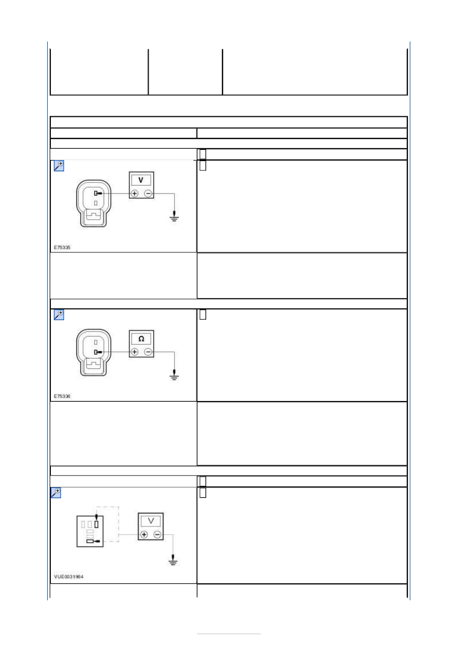
A1: CHECK POWER TO THE HORN

Disconnect Horn C1RH02. 

1 

Measure the voltage between the horn C1RH02 pin 
2, circuit GBB31B (BU/OG), harness side and 

ground while pressing the horn switch. 

2 

Is the voltage greater than 10 volts? 
Yes 

GO to A2

.  

No 

GO to A3

.  

A2: CHECK GROUND TO THE HORN

Measure the resistance between the horn C1RH02 
pin 1, circuit GD312G (BK/VT), harness side and 

ground. 

1 

Is the resistance less than 5 ohms? 
Yes 

INSTALL a new horn. TEST the system for normal 
operation. 

No 

REPAIR circuit GD312G (BK/VT). TEST the system 
for normal operation. 

A3: CHECK POWER TO THE HORN RELAY

Disconnect Horn Relay R9. 

1 

Measure the voltage between the horn relay R9 pin 
1, harness side and ground; and horn relay R9 pin 

3, harness side and ground. 

2 

Are the voltages greater than 10 volts? 


Yes 

GO to A4

.  

No 

INSTALL a new BJB. TEST the system for normal 
operation. 

A4: CHECK HORN SWITCH CIRCUIT FOR OPEN

Measure the resistance between the horn relay R9 
pin 2, circuit CRH04A (VT/GN), harness side and 

ground while pressing the horn switch. 

1 

Is the resistance less than 5 ohms? 
Yes 

INSTALL a new horn Relay R9. Test the system for 
normal operation. 

No 

GO to A5

.  

A5: CHECK SUPPLY TO THE CJB

Disconnect CJB 1BB01. 

1 

Measure the voltage between the CJB 1BB01 pin 1, 
harness side and ground and between the CJB 

1BB01 pin 2, harness side and ground. 

2 

Are the voltages greater than 10 volts? 
Yes 

REPAIR the circuit SBB17. TEST the system for 
normal operation. 

No 

GO to A6

.  

A6: CHECK CIRCUIT CRH04A (BN) FOR OPEN

Measure the resistance between the CJB 1BB01 pin 
46 component side and ground while pressing the 

horn switch. 

1 

Is the resistance less than 5 ohms? 
Yes 

REPAIR the circuit CRH04A. TEST the system for 
normal operation. 

No 

GO to A7

.  

A7: CHECK CJB 1BB01 FOR OPEN

Measure the resistance between the CJB 1BB01 pin 
13, harness side and ground while pressing the 

1 


horn switch. 

Is the resistance less than 5 ohms? 
Yes 

INSTALL a new CJB 1BB01. Test the system for 
normal operation. 

No 

GO to A8

.  

A8: CHECK CIRCUIT CRH03A (BN) FOR OPEN

WARNING: To deactivate the driver air bag, refer to the procedure in section 501-

20B. Failure to follow this instruction, may result in personal injury. 

Disconnect steering wheel module 2R115. 

1 

Measure the resistance between the steering wheel 
module 2R115 pin 4, circuit CRH03-A (BN), harness 

side and horn relay R9 pin 2, CRH03-A (BN), 
harness side. 

2 

Is the resistance less than 5 ohms? 
Yes 

GO to A9

.  

No 

REPAIR the circuit CRH03-A. TEST the system for 
normal operation. 

A9: CHECK CIRCUIT GD133CJ (BK) FOR OPEN

Measure the resistance between the steering wheel 
module 2R115 pin 7, circuit GD133CJ (BK), harness 

side and ground. 

1 

Is the resistance less than 5 ohms? 
Yes 

GO to A10

.  

No 

REPAIR the circuit GD133CJ. TEST the system for 
normal operation. 

A10: CHECK CIRCUIT C2RH02AB FOR OPEN

Disconnect horn switch 2RH03. 

1 

Measure the resistance between the steering wheel 
module 2R115 pin 7, circuit CRH02AB, harness side 

and horn switch 2RH03 pin 1, circuit C2RH02B, 
harness side. 

2 


Is the resistance less than 5 ohms? 
Yes 

GO to A11

.  

No 

REPAIR the circuit C2RH02AB. TEST the system for 
normal operation. 

A11: CHECK THE HORN SWITCH

Measure the resistance between the horn switch 
2RH03 pin 1, component side and horn switch 

2RH03 pin 2, component side while pressing the 
horn switch. 

1 

Is the resistance less than 5 ohms? 
Yes 

GO to A12

.  

No 

INSTALL a new horn switch 2RH03. TEST the 
system for normal operation. 

A12: CHECK CIRCUIT C2RH03AB FOR OPEN

Measure the resistance between the steering wheel 
module pin 4, circuit CRH03AB, harness side and 

horn switch C2RH03 pin 2, circuit C2RH03AB, 
harness side. 

1 

Is the resistance less than 5 ohms? 
Yes 

INSTALL a new steering wheel module. TEST the 
system for normal operation. 

No 

REPAIR the circuit C2RH03AB. TEST the system for 
normal operation. 


Content   ..  700  701  702  703   ..