Ford Galaxy / Ford S-MAX. Manual - part 401
 

  Index      Ford     Ford Galaxy / Ford S-MAX - service repair manual 2006 year


Search            


Content   ..  399  400  401  402   ..


Ford Galaxy / Ford S-MAX. Manual - part 401


With the engine at idle, is the voltage greater than 10 
volts? 
Yes 

INSTALL a new turbocharger vacuum control 
solenoid. TEST the system for normal operation. 

No 

Continue the diagnostic of the engine management 
system using WDS. 

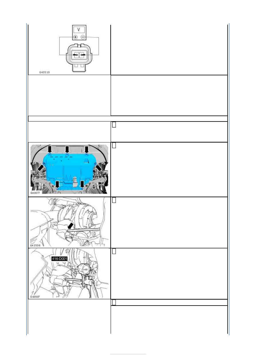
C6: CHECK THE VACUUM DIAPHRAGM UNIT FOR LEAKS

Raise and support the vehicle. For additional 
information,  

REFER to: 

Lifting

 (100-02 Jacking and Lifting, 

Description and Operation). 

1 

Remove the engine undershield. 

Rotate the locking tangs counterclockwise. 

2 

Disconnect the vacuum line from the vacuum 
diaphragm unit. 

3 

Install the special tool to the vane adjustment 
diaphragm unit. 

4 

Operate the special tool and observe the reading. 

5 

Does the special tool hold vacuum? 
Yes 

INSTALL a new vacuum line. TEST the system for 
normal operation. 

No 


INSTALL a new turbocharger.  
REFER to: 

Turbocharger

 (303-04J Fuel Charging 

and Controls - Turbocharger - 2.0L Duratorq-TDCi 
(85kW/115PS) - DW/2.0L Duratorq-TDCi 
(100kW/136PS) - DW/2.0L Duratorq-TDCi 
(103kW/140PS) - DW, Emission Requirements: 
Stage IV, Removal and Installation). 
TEST the system for normal operation. 

Fuel Charging and Controls - 
Turbocharger - 2.0L Duratorq-TDCi 
(85kW/115PS) - DW/2.0L Duratorq-TDCi 
(100kW/136PS) - DW/2.0L Duratorq-
TDCi (103kW/140PS) - DW, Emission 
Requirements: Stage IV - Turbocharger

S-MAX/Galaxy 2006.5 (02/2006-)


Print


Removal and Installation 

Removal 

NOTE: Removal steps in this procedure may contain installation details. 

1. Refer to: 

Catalytic Converter

 (309-00E Exhaust 

System - 2.0L Duratorq-TDCi (85kW/115PS) - 
DW/2.0L Duratorq-TDCi (100kW/136PS) - 
DW/2.0L Duratorq-TDCi (103kW/140PS) - DW, 
Emission Requirements: Stage IV, Removal and 
Installation). 

2. Lower the vehicle. 

3. Torque: 9 Nm 

4. Raise and support the vehicle. 

Refer to: 

Lifting

 (100-02 Jacking and Lifting, 

Description and Operation). 

5.

CAUTION: Make sure that the inside of 

the pipe ends are clean and free of oil 
residue. 

3. Torque: 3 Nm 
4. Torque: 10 Nm 
5. Torque: 15 Nm 
6. Torque: 15 Nm 


Installation 

6.   

1. Torque: 40 Nm 
2. Torque: 10 Nm 
3. Torque: 25 Nm 
4. Torque: 28 Nm 

1.

NOTE: Make sure that a new component is 
installed. 

Install the filter into the turbocharger oil supply 
tube banjo bolt. 

2. To install, reverse the removal procedure. 


Content   ..  399  400  401  402   ..