Ford Ranger EV (2001 year). Manual - part 128
 

  Index      Ford     Ford Ranger EV - service repair manual 2001 year


Search            


Content   ..  126  127  128  129   ..


Ford Ranger EV (2001 year). Manual - part 128


414-03A-108

414-03A-108

High Voltage/Traction Battery

REMOVAL AND INSTALLATION (Continued)

3.

WARNING: The nominal voltage of

the traction battery is 312 volts. The buffer
zone must be set up and insulated rubber
gloves and a face shield must be worn.
Failure to follow these precautions may
result in severe personal injury or  death. 
Observe the EV-specific precautions. Refer to 

Section 100-00

.

1 Set up the buffer zone.
2 Test and wear the insulated rubber gloves.
3 Wear the face shield.

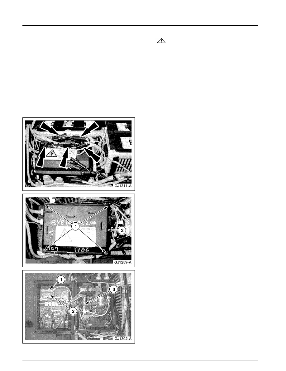
4. Pull the connectors from the top of the

contactor box.

5. Open the contactor box.

1 Remove the four screws.
2 Open the contactor box.

6. Use a fuse puller to remove the necessary fuse.

1 25A Charger Fuse
2 10A Heater Fuse
3 40A Auxiliary Fuse

414-03A-109

414-03A-109

High Voltage/Traction Battery

REMOVAL AND INSTALLATION (Continued)

Installation

1. To install, reverse the removal procedure.

•

Apply Locktite 242 to the 22 traction
battery cover bolts.

HVPDB Fuses

Removal

1. Disconnect the traction battery auxiliary load

high-voltage connector. Refer to 

 Section

100-05

.

2. Remove the high-voltage power distribution box

(HVPDB) cover.
1 Remove the four screws.
2 Remove the cover.

414-03A-110

414-03A-110

High Voltage/Traction Battery

REMOVAL AND INSTALLATION (Continued)

3. Remove the HVPDB fuse safety cover.

1 Remove the two screws.
2 Remove the cover.

4. Use a fuse puller to remove the necessary fuse.

1 10A Power Steering Fuse
2 25A Positive Temperature Coefficient (PTC)

Heater Fuse

3 25A A/C Fuse
4 10A DC/DC Fuse

Installation

1. To install, reverse the removal procedure.

414-03A-111

414-03A-111

High Voltage/Traction Battery

REMOVAL AND INSTALLATION (Continued)

High Voltage Power Distribution Box (HVPDB)

Removal

1. Remove the positive temperature coefficient

(PTC) module. Refer to 

 Section 412-04

.

2. Disconnect the power steering pump electrical

connector.

3. Disconnect the electrical connectors.


Content   ..  126  127  128  129   ..