Ford Ranger EV. Electric Manual - part 9
 

  Index      Ford     Ford Ranger EV - Electric manual 1998 year


Search            


Content   ..  7  8  9  10   ..


Ford Ranger EV. Electric Manual - part 9


LESSON 1: VEHICLE OVERVIEW

1-33

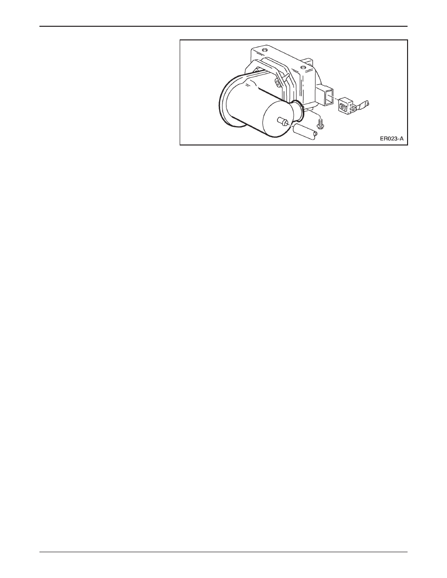
Motor Driven Vacuum Pump

•

A motor driven vacuum pump is mounted beneath the

battery charger.

•

The anti-lock braking system (ABS) is a 4-sensor 3-channel

system.

•

ABS components include:

– an electronic control unit (ECU).

– an Explorer hydraulic control unit (HCU).

– a Ranger mounting bracket.

•

The ABS system sends active line output to the TIM for use with

the regenerative braking system.

•

All of the electric components in the braking system operate off

low voltage circuits.

LESSON 1: VEHICLE OVERVIEW

1-34

Regenerative Braking System (RBS)

Regenerative Braking System (RBS)

•

In a conventional friction braking system, the kinetic energy of

deceleration is transformed into heat.

– This heat is dissipated into the surrounding air.

•

The function of the regenerative braking system (RBS) is to

recover some of this kinetic energy during deceleration and

improve overall vehicle efficiency.

•

Regenerative braking is accomplished by using vehicle

deceleration to drive the motor/transaxle.

– This causes the motor to act as a generator and convert vehicle

kinetic energy into electrical energy that is stored by the traction

battery.

ER024-A

Electrical
energy

Kinetic
energy

LESSON 1: VEHICLE OVERVIEW

1-35

•

The accelerator pedal and the brake pedal are inputs of the RBS.

•

RBS supplements the hydraulic braking system.

•

The RBS operates when the vehicle is moving either forward or

backward.

•

It is possible for RBS motor torque to cause rear wheel slip in

certain circumstances.

– To prevent excessive wheel slip, the RBS is designed to work

with the anti-lock brake system (ABS) module.

– Whenever an ABS event occurs, the ABS module signals the

TIM, which reduces regenerative braking.

– The RBS is returned to its prior state after the ABS event.

NOTE: The IAA triggers the red BRAKE warning lamp in the

instrument cluster if an RBS fault occurs. The vehicle can be safely

operated without RBS.

LESSON 1: VEHICLE OVERVIEW

1-36

ELECTRONIC THROTTLE CONTROL

ER025-A

1

2

Electronic Throttle Control Components

Item

Description

1

Accelerator Position Sensor (APS)

2

Accelerator Pedal Assembly

•

Electronic throttle control is in use on vehicles other than

Electric Ranger.

•

On the Electric Ranger, electronic throttle control replaces the

cable between the accelerator pedal and the powertrain.

•

Instead of a mechanical request for power, electronic throttle

control uses electrical signals.

•

The sensing component of electronic throttle control is an

accelerator position sensor (APS) mounted to the accelerator

pedal assembly.

– Three potentiometers in the APS sense the position of the

accelerator pedal.

– The APS sends signals to the TIM, which commands the

motor/transaxle to respond accordingly.


Content   ..  7  8  9  10   ..