Ford Ranger EV. Electric Manual - part 5
 

  Index      Ford     Ford Ranger EV - Electric manual 1998 year


Search            


Content   ..  3  4  5  6   ..


Ford Ranger EV. Electric Manual - part 5


LESSON 1: VEHICLE OVERVIEW

1-17

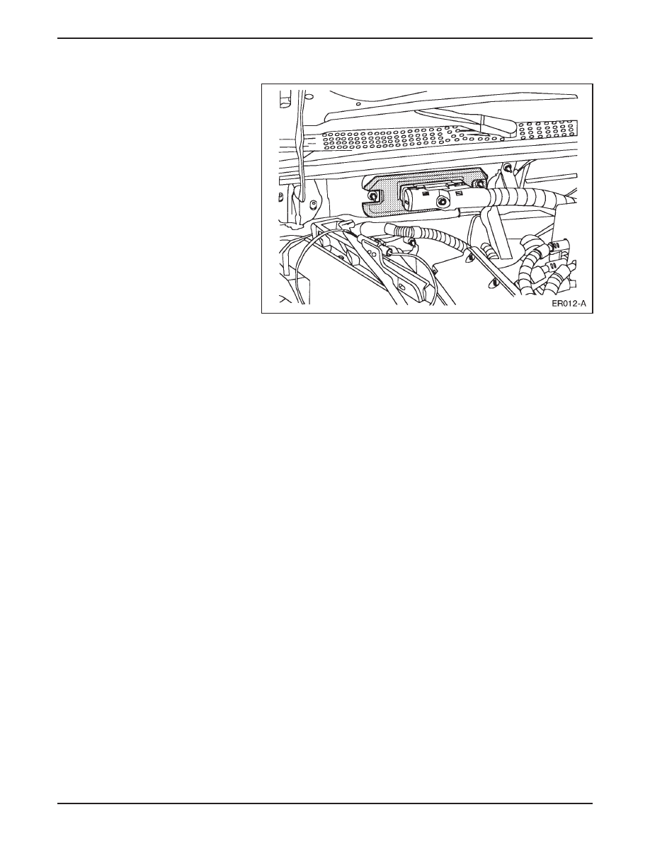
INTERFACE ADAPTER ASSEMBLY (IAA)

Interface Adapter Assembly (IAA)

•

The interface adapter assembly (IAA) is located on the bulkhead

under the instrument panel, the same location as the gasoline-

powered Ranger EEC-V module.

•

The IAA is a low voltage multi-function module that manages the

climate control system, the auxiliary systems and most instrument

cluster gauges and lamps.

•

The IAA is networked with the TIM and the BCM to support

instrument cluster functions, contactor box operations, and

diagnostics.

•

The IAA diagnostics are accessible through the OBD-II diagnostic

connector under the instrument panel next to the steering column.

•

Diagnostic functions as well as parameter identification (PID) data

and active command modes are available.

•

Based on operator and vehicle demands, the IAA controls these

functions:

– High voltage A/C compressor (optional).

– High voltage positive temperature coefficient (PTC) heater.

– Air distribution blend door and climate control blower fan

motor.

– Power steering.

– DC/DC converter.

– Vacuum pump.

– Liquid cooling system coolant pump and two-speed radiator fan.

– Instrument cluster operation.

LESSON 1: VEHICLE OVERVIEW

1-18

INPUTS

INTERFACE

ADAPTER

ASSEMBLY

(IAA)

OUTPUTS

Blower Motor Speed

Emergency Power Off
(EPO)

A/C Pressure Sensor

Vacuum Pressure 
Sensor

Coolant Temperature
Sensor

Brake Fluid Level 
Switch

PTC Heater Switching 
Module

Steering Wheel
Sensors

PTC Heater Cores

Emergency Power Off
(EPO)

Vacuum Pump

A/C Compressor

DC/DC Converter

Cooling Fan Relay

Auxiliary Contactor 
Relay

Power Steering 
Control

Instrument Gauges
and Lights

Air Distribution
Blend Doors

LESSON 1: VEHICLE OVERVIEW

1-19

MOTOR/TRANSAXLE

Motor/Transaxle Assembly

•

The motor/transaxle is mounted just behind the traction battery.

•

The motor/transaxle assembly consists of a:

– four-pole, three phase AC induction motor.

– single-speed transaxle with a planetary gearset.

•

The motor/transaxle supplies power through halfshafts to the

rear wheels.

– A peak power of 67 kW (90 hp) is produced at 190 Nm

(140 lb ft) torque.

•

The assembly is packaged in an aluminum case and weighs

approximately 91 kg (200 lb).

LESSON 1: VEHICLE OVERVIEW

1-20

Motor

Motor Components

•

The AC induction motor consists of a:

– stator (A).

– cast aluminum rotor (B).

– rotor speed sensor (C).

•

The motor has a maximum operating speed of 13,000 rpm and

maximum current draw of 305 amps.

ER014-A

A

B

C


Content   ..  3  4  5  6   ..