Ford Focus RS (2011 year). Instruction - part 20
 

  Index      Ford     Ford Focus RS - service repair manual (2011 year) in english


Search            


Content   ..  18  19  20  21   ..


Ford Focus RS (2011 year). Instruction - part 20


DETAILS/RESULTS/ACTIONS

TEST CONDITIONS

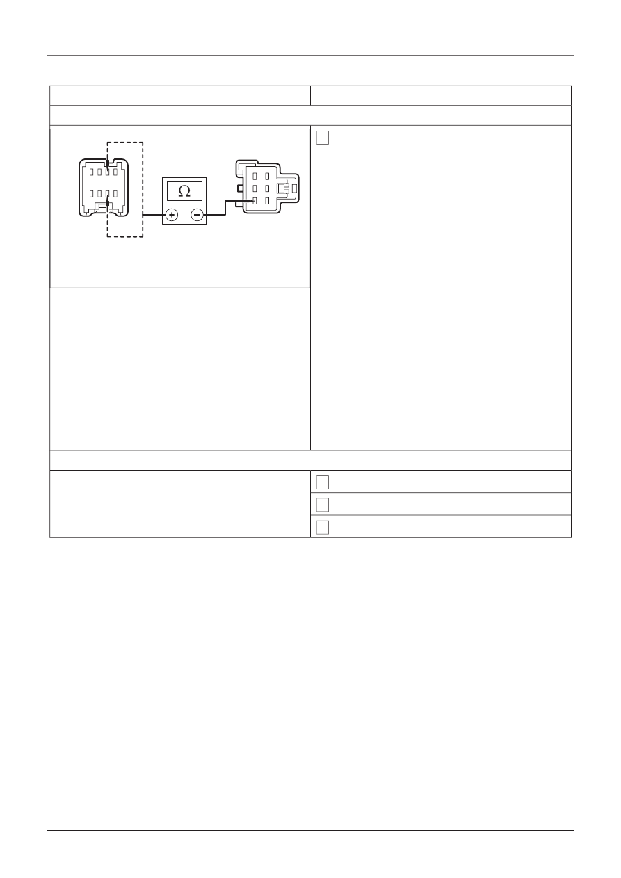
C4: CHECK CIRCUIT 32-AD6 (WH) FOR CONTINUITY

1 Measure the resistance between the:

Left-hand drive vehicles
• Exterior mirror control switch C741 pin 7, circuit

32-AD6 (WH), harness side and the driver side
exterior mirror C808 pin 3, circuit 32-AD6 (WH),
harness side.

E0037298

Right-hand drive vehicles
• Exterior mirror control switch C741 pin 3, circuit

32-AD6C (WH), harness side and the driver side
exterior mirror C808 pin 3, circuit 32-AD6C (WH),
harness side.

• Is the resistance less than 5 ohms?

ൺ

Yes

INSTALL a new driver side exterior mirror.

REFER to: Exterior Mirror

(501-09 Rear View

Mirrors, Removal and Installation).

TEST the system for normal operation.

ൺ

No

REPAIR circuit 32-AD6 (WH) or circuit 32-
AD6C (WH). TEST the system for normal
operation.

C5: CHECK THE DRIVER SIDE EXTERIOR MIRROR LEFT/RIGHT CIRCUIT

1 Ignition switch in position 0.

2 Disconnect Driver Side Exterior Mirror C808.

3 Ignition switch in position II.

G167553en

501-09-

10

Rear View Mirrors

501-09-

10

DIAGNOSIS AND TESTING

DETAILS/RESULTS/ACTIONS

TEST CONDITIONS

4 Select the driver side exterior mirror. While

operating the exterior mirror control switch LEFT
and RIGHT, measure the voltage between the:

Left-hand drive vehicles
• Driver side exterior mirror C808 pin 2, circuit 33-

AD8 (YE/BU), harness side and the driver side
exterior mirror C808 pin 3, circuit 32-AD6 (WH),
harness side.

E0037449

Right-hand drive vehicles
• Driver side exterior mirror C808 pin 2, circuit 33-

AD8C (YE/BU), harness side and the driver side
exterior mirror C808 pin 3, circuit 32-AD6C (WH),
harness side.

• Is the voltage greater than 10 volts when the

exterior mirror control switch is moved to the
LEFT position and is the polarity reversed
when moved to the RIGHT position?

ൺ

Yes

INSTALL a new driver side exterior mirror.

REFER to: Exterior Mirror

(501-09 Rear View

Mirrors, Removal and Installation).

TEST the system for normal operation.

ൺ

No

GO to C6.

C6: CHECK CIRCUIT 33-AD8 (YE/BU) FOR CONTINUITY

1 Ignition switch in position 0.

2 Disconnect Exterior Mirror Control Switch C741.

3 Measure the resistance between the:

Left-hand drive vehicles
• Exterior mirror control switch C741 pin 6, circuit

33-AD8 (YE/BU), harness side and the driver
side exterior mirror C808 pin 2, circuit 33-AD8
(YE/BU), harness side.

E0037302

Right-hand drive vehicles
• Exterior mirror control switch C741 pin 2, circuit

33-AD8C (YE/BU), harness side and the driver
side exterior mirror C808 pin 2, circuit 33-AD8C
(YE/BU), harness side.

• Is the resistance less than 5 ohms?

ൺ

Yes

GO to C7.

ൺ

No

REPAIR circuit 33-AD8 (YE/BU) or circuit 33-
AD8C (YE/BU). TEST the system for normal
operation.

G167553en

501-09-

11

Rear View Mirrors

501-09-

11

DIAGNOSIS AND TESTING

DETAILS/RESULTS/ACTIONS

TEST CONDITIONS

C7: CHECK CIRCUIT 32-AD6 (WH) FOR CONTINUITY

1 Measure the resistance between the:

Left-hand drive vehicles
• Exterior mirror control switch C741 pin 7, circuit

32-AD6 (WH), harness side and the driver side
exterior mirror C808 pin 3, circuit 32-AD6 (WH),
harness side.

E0037298

Right-hand drive vehicles
• Exterior mirror control switch C741 pin 3, circuit

32-AD6C (WH), harness side and the driver side
exterior mirror C808 pin 3, circuit 32-AD6C (WH),
harness side.

• Is the resistance less than 5 ohms?

ൺ

Yes

INSTALL a new driver side exterior mirror.

REFER to: Exterior Mirror

(501-09 Rear View

Mirrors, Removal and Installation).

TEST the system for normal operation.

ൺ

No

REPAIR circuit 32-AD6 (WH) or circuit 32-AD6
(WH). TEST the system for normal operation.

C8: CHECK THE PASSENGER SIDE MIRROR UP/DOWN CIRCUIT

1 Ignition switch in position 0.

2 Disconnect Passenger Side Exterior Mirror

C822.

3 Ignition switch in position II.

G167553en

501-09-

12

Rear View Mirrors

501-09-

12

DIAGNOSIS AND TESTING

DETAILS/RESULTS/ACTIONS

TEST CONDITIONS

4 Select the passenger side exterior mirror. While

operating the exterior mirror control switch UP
and DOWN, measure the voltage between the
passenger side exterior mirror C822 pin 1, circuit
34-AD10 (BU/YE), harness side and the
passenger side exterior mirror C822 pin 3, circuit
32-AD9 (WH/GN), harness side.

• Is the voltage greater than 10 volts when the

exterior mirror control switch is moved to the
UP position and is the polarity reversed when
moved to the DOWN position?

ൺ

Yes

E55391

INSTALL a new passenger side exterior
mirror.

REFER to: Exterior Mirror

(501-09 Rear View

Mirrors, Removal and Installation).

TEST the system for normal operation.

ൺ

No

GO to C9.

C9: CHECK CIRCUIT 34-AD10 (BU/YE) FOR CONTINUITY

1 Ignition switch in position 0.

2 Disconnect Exterior Mirror Control Switch C741.

3 Measure the resistance between the:

Left-hand drive vehicles
• Exterior mirror control switch C741 pin 4, circuit

34-AD10 (BU/YE), harness side and the
passenger side exterior mirror C822 pin 1, circuit
34-AD10 (BU/YE), harness side.

E0037300

Right-hand drive vehicles
• Exterior mirror control switch C741 pin 8, circuit

34-AD10C (BU/YE), harness side and the
passenger side exterior mirror C822 pin 1, circuit
34-AD10 (BU/YE), harness side.

• Is the resistance less than 5 ohms?

ൺ

Yes

GO to C10.

ൺ

No

REPAIR circuit 34-AD10 (BU/YE) or circuit
34-AD10C (BU/YE). TEST the system for
normal operation.

G167553en

501-09-

13

Rear View Mirrors

501-09-

13

DIAGNOSIS AND TESTING

DETAILS/RESULTS/ACTIONS

TEST CONDITIONS

C10: CHECK CIRCUIT 32-AD9 (WH/GN) FOR CONTINUITY

1 Measure the resistance between the:

Left-hand drive vehicles
• Exterior mirror control switch C741 pin 3, circuit

32-AD9 (WH/GN), harness side and the
passenger side exterior mirror C822 pin 3, circuit
32-AD9 (WH/GN), harness side.

E0037298

Right-hand drive vehicles
• Exterior mirror control switch C741 pin 7, circuit

32-AD9C (WH/GN), harness side and the
passenger side exterior mirror C822 pin 3, circuit
32-AD9 (WH/GN), harness side.

• Is the resistance less than 5 ohms?

ൺ

Yes

INSTALL a new passenger side exterior
mirror.

REFER to: Exterior Mirror

(501-09 Rear View

Mirrors, Removal and Installation).

TEST the system for normal operation.

ൺ

No

REPAIR circuit 32-AD9 (WH/GN) or circuit 32-
AD9C (WH/GN). TEST the system for normal
operation.

C11: CHECK THE PASSENGER SIDE EXTERIOR MIRROR LEFT/RIGHT CIRCUIT

1 Ignition switch in position 0.

2 Disconnect Passenger Side Exterior Mirror

C822.

3 Ignition switch in position II.

G167553en

501-09-

14

Rear View Mirrors

501-09-

14

DIAGNOSIS AND TESTING

DETAILS/RESULTS/ACTIONS

TEST CONDITIONS

4 Select the passenger side exterior mirror. While

operating the exterior mirror control switch LEFT
and RIGHT, measure the voltage between the
passenger side exterior mirror C822 pin 2, circuit
33-AD11 (YE/VT), harness side and the
passenger side exterior mirror C822 pin 3, circuit
32-AD9 (WH/GN), harness side.

• Is the voltage greater than 10 volts when the

exterior mirror control switch is moved to the
LEFT position and is the polarity reversed
when moved to the RIGHT position.

ൺ

Yes

E0037449

INSTALL a new passenger side exterior
mirror.

REFER to: Exterior Mirror

(501-09 Rear View

Mirrors, Removal and Installation).

TEST the system for normal operation.

ൺ

No

GO to C12.

C12: CHECK CIRCUIT 33-AD11 (YE/VT) FOR CONTINUITY

1 Ignition switch in position 0.

2 Disconnect Exterior Mirror Control Switch C741.

3 Measure the resistance between the:

Left-hand drive vehicles
• Exterior mirror control switch C741 pin 2, circuit

33-AD11 (YE/VT), harness side and the
passenger side exterior mirror C822 pin 2, circuit
33-AD11 (YE/VT), harness side.

E0037302

Right-hand drive vehicles
• Exterior mirror control switch C741 pin 6, circuit

33-AD11C (YE/VT), harness side and the
passenger side exterior mirror C822 pin 2, circuit
33-AD11 (YE/VT), harness side.

• Is the resistance less than 5 ohms?

ൺ

Yes

GO to C13.

ൺ

No

REPAIR circuit 33-AD11 (YE/VT) or circuit 33-
AD11C (YE/VT). TEST the system for normal
operation.

G167553en

501-09-

15

Rear View Mirrors

501-09-

15

DIAGNOSIS AND TESTING

DETAILS/RESULTS/ACTIONS

TEST CONDITIONS

C13: CHECK CIRCUIT 32-AD9 (WH/GN) FOR CONTINUITY

1 Measure the resistance between the:

Left-hand drive vehicles
• Exterior mirror control switch C741 pin 3, circuit

32-AD9 (WH/GN), harness side and the
passenger side exterior mirror C822 pin 3, circuit
32-AD9 (WH/GN), harness side.

E0037298

Right-hand drive vehicles
• Exterior mirror control switch C741 pin 7, circuit

32-AD9C (WH/GN), harness side and the
passenger side exterior mirror C822 pin 3, circuit
32-AD9 (WH/GN), harness side.

• Is the resistance less than 5 ohms?

ൺ

Yes

INSTALL a new passenger side exterior
mirror.

REFER to: Exterior Mirror

(501-09 Rear View

Mirrors, Removal and Installation).

TEST the system for normal operation.

ൺ

No

REPAIR circuit 32-AD9 (WH/RD) or circuit 32-
AD9C (WH/RD). TEST the system for normal
operation.

PINPOINT TEST D : THE HEATED EXTERIOR MIRROR IS INOPERATIVE

DETAILS/RESULTS/ACTIONS

TEST CONDITIONS

NOTE: Use a digital multimeter for all electrical measurements.

D1: CHECK THE OPERATION OF THE HEATED REAR WINDOW

1 Ignition switch in position II.

2 Operate the heated rear window control switch.

• Does the heated rear window function

correctly?

ൺ

Yes

GO to D2.

ൺ

No

REPAIR the heated rear window.

REFER to: Glass, Frames and Mechanisms

-

Vehicles With: Global Closing

(501-11

Glass, Frames and Mechanisms, Diagnosis
and Testing).

D2: CHECK THE VOLTAGE TO THE INOPERATIVE EXTERIOR MIRROR

1 Ignition switch in position 0.

G167553en

501-09-

16

Rear View Mirrors

501-09-

16

DIAGNOSIS AND TESTING

DETAILS/RESULTS/ACTIONS

TEST CONDITIONS

2 Disconnect Inoperative Exterior Mirror C808 or

C822.

3 Ignition switch in position II.

4 Operate the heated rear window control switch.

5 Measure the voltage between the:

• Driver side exterior mirror C808 pin 4, circuit

15S-HB35 (GN/BK), harness side and ground.

• Passenger side exterior mirror C822 pin 4, circuit

15S-HB36 (GN/OG), harness side and ground.

E55392

• Is the voltage greater than 10 volts?

ൺ

Yes

GO to D3.

ൺ

No

REPAIR circuit 15S-HB35 (GN/BK) or circuit
15S-HB36 (GN/OG). TEST the system for
normal operation.

D3: CHECK THE INOPERATIVE EXTERIOR MIRROR GROUND CIRCUIT FOR CONTINUITY

1 Ignition switch in position 0.

2 Measure the resistance between the:

• Driver side exterior mirror C808 pin 5, circuit 31-

HB35 (BK), harness side and ground.

• Passenger side exterior mirror C822 pin 5, circuit

31-HB36 (BK), harness side and ground.

E55393

• Is the resistance less than 5 ohms?

ൺ

Yes

INSTALL a new heated exterior mirror glass.
TEST the system for normal operation.

ൺ

No

REPAIR circuit 31-HB35 (BK) or circuit 31-
HB36 (BK). TEST the system for normal
operation.

PINPOINT TEST E : THE AUTO-DIMMING INTERIOR MIRROR DOES NOT OPERATE CORRECTLY

DETAILS/RESULTS/ACTIONS

TEST CONDITIONS

NOTE: Use a digital multimeter for all electrical measurements.

E1: CHECK FOR CONTINUITY BETWEEN THE AUTO-DIMMING INTERIOR MIRROR AND GROUND

1 Disconnect Auto-dimming Interior Mirror C742.

G167553en

501-09-

17

Rear View Mirrors

501-09-

17

DIAGNOSIS AND TESTING


Content   ..  18  19  20  21   ..