Ford F150 Pickup. Instruction - part 691


  Index      Ford     Ford F150 Pickup - service and repair instruction 2003 year


Search            copyright infringement  


Content   ..  689  690  691  692   ..


Ford F150 Pickup. Instruction - part 691


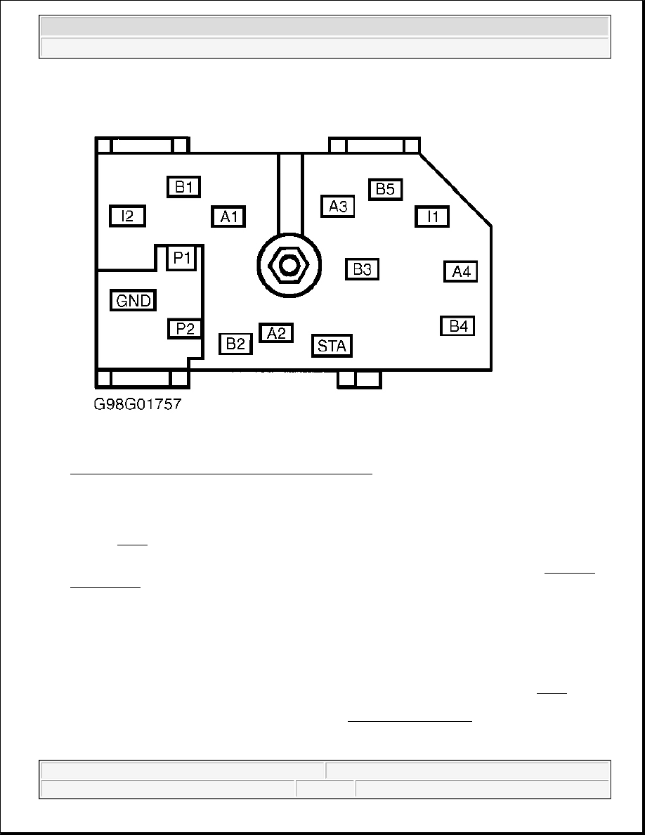
Fig. 6: Identifying Ignition Switch Connector Terminals 
Courtesy of FORD MOTOR CO. 

5. Remove battery junction box fuse No. 111 (40-amp). Measure resistance of Light Green/Violet wire 

between ignition switch harness connector terminal B5 and output side of battery junction box fuse No. 
111. See Fig. 6 . If resistance is less than 5 ohms, replace ignition switch. See appropriate STEERING 
COLUMN SWITCHES article in ACCESSORIES & EQUIPMENT. If resistance is 5 ohms or greater, 
repair open in Light Green/Violet wire between ignition switch and battery junction box. See WIRING 
DIAGRAMS
 . Check system operation.  

6. Turn ignition switch to LOCK position. Disconnect starter motor relay connector (Tan/Red wire). 

Measure voltage between ground and Tan/Red wire at starter motor relay connector terminal while 
holding ignition switch in START position. If battery voltage is present, replace starter motor relay. 
Check system operation. If battery voltage is not present, go to next step (A/T models) or go to step 12 
(M/T models).  

7. Disconnect Digital Transmission Range (DTR) sensor 12-pin connector. Measure resistance of Tan/Red 

wire between DTR sensor connector terminal No. 12 and starter motor relay connector. See Fig. 7 . If 
resistance is less than 5 ohms, go to next step. If resistance is 5 ohms or greater, repair open in Tan/Red 
wire between DTR sensor and starter motor relay. See WIRING DIAGRAMS . Check system operation. 


2003 Ford Pickup F150 

2003 STARTING & CHARGING SYSTEMS Starters - F150 Pickup


Fig. 7: Identifying Digital Transmission Range Sensor Connector Terminals 
Courtesy of FORD MOTOR CO. 

8. Check DTR sensor adjustment. See DIGITAL TRANSMISSION RANGE SENSOR under 

ADJUSTMENTS. If DTR sensor is adjusted properly, go to next step. If DTR sensor is not adjusted 
properly, adjust as necessary. Check system operation.  

9. Connect a jumper wire between DTR sensor connector terminals No. 12 (Tan/Red wire) and No. 10 

(Dark Blue/Orange wire). See Fig. 7 . Attempt to start vehicle. If vehicle does not start, go to next step. If 
vehicle starts, replace DTR sensor. See DIGITAL TRANSMISSION RANGE SENSOR under 
REMOVAL & INSTALLATION. Check system operation.  

10. Disconnect Clutch Pedal Position (CPP) jumper 6-pin connector. Measure resistance of Dark 

Blue/Orange wire between DTR connector terminal No. 10 and CPP jumper connector terminal No. 2. 
See Fig. 7 and Fig. 8 . If resistance is less than 5 ohms, go to next step. If resistance is 5 ohms or greater, 
repair open in Dark Blue/Orange wire between DTR sensor and CPP jumper. See WIRING 
DIAGRAMS
 . Check system operation. 


2003 Ford Pickup F150 

2003 STARTING & CHARGING SYSTEMS Starters - F150 Pickup


Fig. 8: Identifying Clutch Pedal Position Switch Or Jumper Connector Terminals 
Courtesy of FORD MOTOR CO. 

11. Measure resistance between CPP jumper terminals No. 1 and 2 (component side). If resistance is 5 ohms 


2003 Ford Pickup F150 

2003 STARTING & CHARGING SYSTEMS Starters - F150 Pickup


or less, go to step 14 . If resistance is greater than 5 ohms, replace CPP jumper. Check system operation.

12. Disconnect starter motor relay connector (Tan/Red wire). Disconnect CPP switch 6-pin connector. 

Measure resistance between Tan/Red wire at starter motor relay connector terminal and CPP switch 
connector terminal No. 2 (Dark Blue/Orange wire). See Fig. 8 . If resistance is less than 5 ohms, 
reconnect starter motor relay and go to next step. If resistance is 5 ohms or greater, repair open in 
Tan/Red wire or Dark Blue/Orange wire between CPP switch and starter motor relay. See 

WIRING 

DIAGRAMS

 . Check system operation.  

13. Connect a jumper wire between CPP switch connector terminals No. 5 (White/Pink wire) and No. 6 

(Gray/Yellow wire). Connect another jumper wire between CPP switch connector terminals No. 1 
(White/Pink wire) and No. 2 (Dark Blue/Orange wire). See Fig. 8 . Attempt to start vehicle. If vehicle 
does not start, go to next step. If vehicle starts, replace CPP switch. Check system operation.  

14. Disconnect central junction box 34-pin connector C270b. Measure resistance of White/Pink wire between 

central junction box connector C270b terminal No. 29 and CPP switch/jumper connector terminal No. 1. 
See Fig. 8 and Fig. 9 . If resistance is less than 5 ohms, replace central junction box. If resistance is 5 
ohms or greater, repair open in White/Pink wire between central junction box and CPP switch/jumper. 
Check system operation. 


2003 Ford Pickup F150 

2003 STARTING & CHARGING SYSTEMS Starters - F150 Pickup


Content   ..  689  690  691  692   ..