Ford F150 Pickup. Instruction - part 1795


  Index      Ford     Ford F150 Pickup - service and repair instruction 2003 year


Search            copyright infringement  


Content   ..  1793  1794  1795  1796   ..


Ford F150 Pickup. Instruction - part 1795


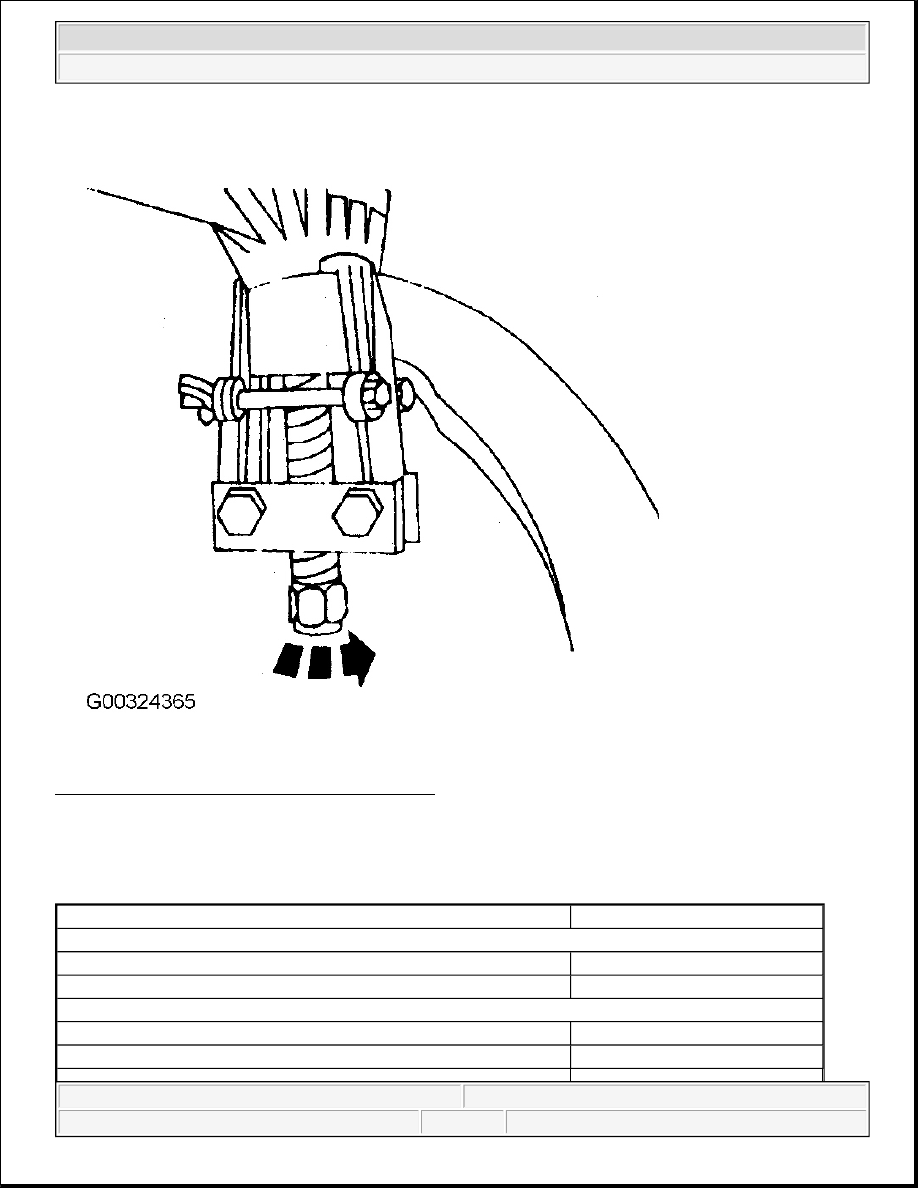
Fig. 8: Separating Upper Ball Joint From Spindle 
Courtesy of FORD MOTOR CO. 

TORQUE SPECIFICATIONS 

TORQUE SPECIFICATIONS 

Application

Ft. Lbs. (N.m)

Ball Joint Nuts

Lower

83-112 (113-153)

Upper

57-76 (77-103)

Control Arm Nut

Lower

121-147 (164-200)

Upper

83-113 (113-153)


2003 Ford Pickup F150 

2002-03 SUSPENSION Front - 4WD Torsion Bar - F150 Pickup


Front Axle Hub Nut 

(1)

188-254 (255-345)

Hub & Bearing Assembly-To-Knuckle Bolts

110-148 (149-201)

Lower Shock Absorber Mounting Nut & Bolt

65-87 (88-118)

Skid Plate Bolts

10-12 (14-17)

Stabilizer Bar Bolts/Nuts

Bracket Bolt

19-25 (26-34)

Link End

16-21 (21-29)

Tie Rod End Nut

57-76 (77-103)

Torsion Bar-To-Crossmember

Bolt

29-40 (40-54)

Nut

39-53 (53-72)

Upper Shock Absorber Mounting Bolt

22-29 (30-40)

Wheel Lug Nuts

12 mm

100 (135)

14 mm

150 (204)

INCH Lbs. (N.m)

ABS Sensor Bolt

62-80 (7-9)

ABS Sensor Wire Bracket Bolt

62-80 (7-9)

Brake Disc Shield Bolts

80-106 (9-12)

(1)

DO NOT back off retainer nut to install NEW cotter pin. After reaching specification, tighten nut 
only enough to align slot.

(2)

Tighten wheel lug nuts an additional 1/8 to 1/4 turn.


2003 Ford Pickup F150 

2002-03 SUSPENSION Front - 4WD Torsion Bar - F150 Pickup


2003-04 SUSPENSION 

General Diagnosis - H2 

TRIM HEIGHT SPECIFICATIONS 

Fig. 1: Trim Height Specifications 
Courtesy of GENERAL MOTORS CORP. 

DIAGNOSTIC INFORMATION 

DIAGNOSTIC STARTING POINT - SUSPENSION GENERAL DIAGNOSIS 

Begin the system diagnosis by reviewing the system Description & Operation. See REAR SUSPENSION - 
H2
 . Reviewing the Description and Operation information will help you determine the correct symptom 
diagnostic procedure when a malfunction exists. Reviewing the Description and Operation information, and the 
vehicle RPO, will also help you determine if the condition described by the customer is normal operation. See 
SYMPTOMS - SUSPENSION GENERAL DIAGNOSIS in order to identify the correct procedure for 
diagnosing the system and where the procedure is located.  

SYMPTOMS - SUSPENSION GENERAL DIAGNOSIS 

The following steps must be completed before using the symptom tables.  

1. Determine whether the vehicle is equipped with an electrically assisted or active suspension system. 

Perform electrical diagnosis prior to beginning mechanical diagnosis.  

2. Review the system description and operation in order to familiarize yourself with the system functions. 

Refer to the appropriate description and operation: 

z

General Description in Front Suspension.  

z

General Description in Rear Suspension.  

Visual/Physical Inspection 

z

Inspect for aftermarket devices which could affect the operation of any of the suspension subsystems.  

z

Inspect the easily accessible or visible system components for obvious damage or conditions which could 
cause the symptom.  

z

Inspect for proper tire size and inflation pressure. 


2004 Hummer H2 

2003-04 SUSPENSION General Diagnosis - H2


2004 Hummer H2 

2003-04 SUSPENSION General Diagnosis - H2


Symptom List 

z

BALL JOINT INSPECTION (LOWER BALL JOINT)  

z

BALL JOINT INSPECTION (UPPER BALL JOINT)  

z

BODY LEANS OR SWAYS IN CORNERS  

z

MEMORY STEER  

z

NOISE DIAGNOSIS - FRONT SUSPENSION  

z

NOISE DIAGNOSIS - REAR SUSPENSION  

z

POOR DIRECTIONAL STABILITY  

z

RIDE DIAGNOSIS  

z

STRUTS OR SHOCK ABSORBERS ON-VEHICLE TESTING  

z

SUSPENSION BOTTOMS  

z

TRIM HEIGHT INSPECTION PROCEDURE  

z

VEHICLE LEADS/PULLS  

z

WHEEL BEARING DIAGNOSIS  

BALL JOINT INSPECTION (LOWER BALL JOINT) 

1. Raise and support the vehicle.  

2. With the wheel and tire on the vehicle, lift the suspension corner by hand to determine if any looseness is 

present. If vertical free play is experienced proceed with the following instructions.  

3. Remove the wheel and tire.  

4. Clean and inspect the ball joint seals for cuts or tears. If the ball joint seals are damaged, replace the ball 

joint.  

5. Install and position the dial indicator from J-8001 against the end of the ball joint. See SPECIAL 

TOOLS 


2004 Hummer H2 

2003-04 SUSPENSION General Diagnosis - H2


Content   ..  1793  1794  1795  1796   ..