Ford F150 Pickup. Instruction - part 1721


  Index      Ford     Ford F150 Pickup - service and repair instruction 2003 year


Search            copyright infringement  


Content   ..  1719  1720  1721  1722   ..


Ford F150 Pickup. Instruction - part 1721


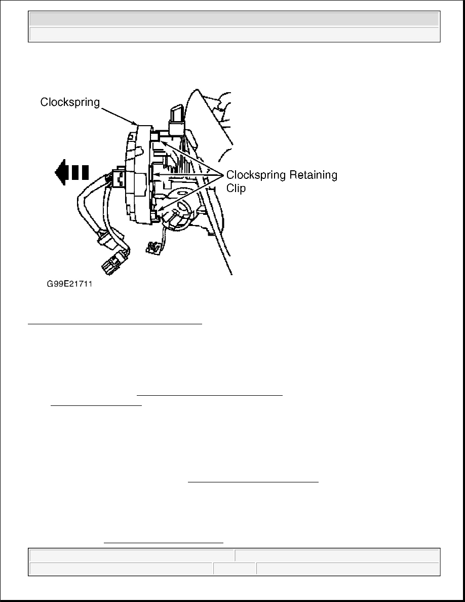
Fig. 8: Locating Clockspring Retaining Clips 
Courtesy of FORD MOTOR CO. 

DRIVER-SIDE AIR BAG MODULE 

Removal 

1. Before proceeding, see AIR BAG SAFETY PRECAUTIONS . Disable air bag system. See 

DISABLING SYSTEM under DISABLING & ACTIVATING AIR BAG SYSTEM.  

2. Remove back cover plugs from rear of steering wheel. Remove bolts retaining air bag module to steering 

wheel. On Lightning model, disconnect air bag module connector. On all other models, disconnect horn 
switch and air bag electrical connector. Remove air bag module from vehicle.  

3. Remove air bag simulator from clockspring harness connector and reconnect connectors. Connect Air 

Bag Simulator (418-F088/105-R0012) to harness side of upper clockspring connector at top of steering 
column. Connect negative battery cable. With air bag simulators installed at all deployable devices, 
perform system operation check. See SYSTEM OPERATION CHECK . Disconnect negative battery 
cable. Wait at least one minute for back-up power supply to deplete stored energy.  

Installation 

Remove air bag simulator from clockspring connector. To install, reverse removal procedure. Tighten fasteners 
to specification. See TORQUE SPECIFICATIONS . Connect negative battery cable. With air bag simulators 


2003 Ford Pickup F150 

2003 ACCESSORIES/SAFETY EQUIPMENT Air Bag Restraint Systems - F150 Pickup


installed at all remaining deployable devices, perform system operation check. See SYSTEM OPERATION 
CHECK
 . Activate air bag system. See ACTIVATING SYSTEM under DISABLING & ACTIVATING AIR 
BAG SYSTEM. 

FRONT SEAT 

Removal Percent Seat With Seat Integrated Restraints) 

Before proceeding, see AIR BAG SAFETY PRECAUTIONS . Disable air bag system. See DISABLING 
SYSTEM
 under DISABLING & ACTIVATING AIR BAG SYSTEM. Disconnect front seat electrical 
connectors. Remove fifth foot trim cover. Remove anchor bolts. Remove fifth foot anchor bolt. With help from 
an assistant, remove front seat from vehicle. 

Installation 

1. Position front seat in vehicle. Install front seat anchor bolts (DO NOT tighten at this time). 

2. Tighten front anchor bolts to specification. See TORQUE SPECIFICATIONS . Tighten rear anchor 

bolts to specification. Tighten fifth foot anchor bolt to specification. Install anchor bolt caps. Install fifth 
foot trim cover. Remove pretensioner simulator from appropriate connector and reconnect connectors.  

3. Connect negative battery cable. With air bag simulators installed at all remaining deployable devices, 

perform system operation check. See SYSTEM OPERATION CHECK . Activate air bag system. See 
ACTIVATING SYSTEM under DISABLING & ACTIVATING AIR BAG SYSTEM.  

Removal & Installation Percent Seat With Seat Integrated Restraints) 

Information is not available. Removal procedure is similar to 40 percent seat. See REMOVAL (40 PERCENT 
SEAT WITH SEAT INTEGRATED RESTRAINTS)
 . 

Removal & Installation (Captian's Seat With Seat Integrated Restraints) 

Information is not available. Removal procedure is similar to 40 percent seat. See REMOVAL (40 PERCENT 
SEAT WITH SEAT INTEGRATED RESTRAINTS)
 . 

Removal & Installation (Without Seat Integrated Restraints) 

Before proceeding, see AIR BAG SAFETY PRECAUTIONS . On models with captain chair and 40 percent 
seat, position seat forward to access anchor nuts and bolts. If equipped with power seats, raise seat to maximum 
height. On all models, disconnect negative battery cable. Remove front seat anchor nuts and bolts. Disconnect 

WARNING:

Certain models are equipped with seat integrated restraints with seat belt 
buckle pretensioners. Personal injury is possible. Follow all air bag 
system precautions when removing front seats equipped with 
pretensioners.

NOTE:

Anchor nuts and bolt must be tightened in specific order.


2003 Ford Pickup F150 

2003 ACCESSORIES/SAFETY EQUIPMENT Air Bag Restraint Systems - F150 Pickup


electrical connectors. With help from an assistant, remove front seat from vehicle. To install, reverse removal 
procedure. Tighten front seat anchor nuts and bolts to specification. See TORQUE SPECIFICATIONS . 

GENERIC ELECTRONIC MODULE (GEM) (WITHOUT SEAT INTEGRATED RESTRAINTS) 

Removal & Installation 

1. Before proceeding, see AIR BAG SAFETY PRECAUTIONS . Disconnect negative battery cable. 

Remove upper instrument panel steering column cover. Remove instrument panel fuse/relay panel cover. 
Remove bolts and disconnect parking brake release lever. Remove bolts and disconnect hood release 
lever.  

2. Remove bolts and lower instrument panel steering column cover. Loosen screws and remove 2 large 

bulkhead electrical connectors from instrument panel fuse junction panel. See Fig. 9 . Remove instrument 
panel fuse junction panel bolts. See Fig. 10 . Disconnect GEM electrical connectors. Remove screws and 
separate GEM from instrument panel fuse junction panel.  

3. To install, reverse removal procedure. Tighten fasteners to specification. See TORQUE 

SPECIFICATIONS . Connect negative battery cable. Check AIR BAG warning light for proper system 
function. See SYSTEM OPERATION CHECK 

NOTE:

If installing new GEM, module configuration information must downloaded from 
existing GEM to scan tool. After new GEM has been installed, use scan tool to 
upload configuration data to new module.


2003 Ford Pickup F150 

2003 ACCESSORIES/SAFETY EQUIPMENT Air Bag Restraint Systems - F150 Pickup


Fig. 9: Identifying Bulkhead Electrical Connectors 
Courtesy of FORD MOTOR CO. 


2003 Ford Pickup F150 

2003 ACCESSORIES/SAFETY EQUIPMENT Air Bag Restraint Systems - F150 Pickup


Content   ..  1719  1720  1721  1722   ..