Ford F150 Pickup. Instruction - part 1631


  Index      Ford     Ford F150 Pickup - service and repair instruction 2003 year


Search            copyright infringement  


Content   ..  1629  1630  1631  1632   ..


Ford F150 Pickup. Instruction - part 1631


pump is located inside reservoir and supplies fuel through fuel pump module manifold to engine and fuel 
pump module jet pump. See Fig. 35 .  

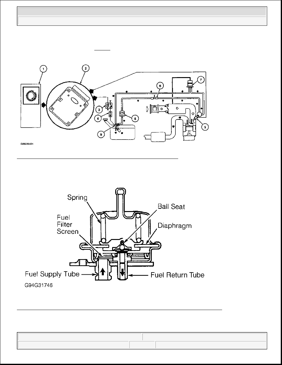
Fig. 32: Identifying Returnable Fuel System Components & Circuits 
Courtesy of FORD MOTOR CO. 

Fig. 33: Cross-Sectional View Of Pressure Regulator Components (Returnable System) 
Courtesy of FORD MOTOR CO. 


2003 Ford Pickup F150 

2003 ENGINE PERFORMANCE Theory & Operation - CNG, Flex-Fuel & Gasoline


Fig. 34: Identifying Fuel Pump Assembly (Returnable Fuel System) 
Courtesy of FORD MOTOR CO. 


2003 Ford Pickup F150 

2003 ENGINE PERFORMANCE Theory & Operation - CNG, Flex-Fuel & Gasoline


Fig. 35: Cross-Sectional View Of Fuel Pump Assembly (Returnable & Electronic Returnless Fuel System)
Courtesy of FORD MOTOR CO.
 

Mechanical Returnless Fuel System 

Electronic returnless fuel system consists of a fuel tank with reservoir, fuel pump, fuel pressure regulator, fuel 
filter, fuel supply line, fuel rail, fuel rail pulse damper, fuel injectors, and Schrader/pressure test port. The 
following list of components and their specific operation corresponds to numbers in illustration. See Fig. 36 

NOTE:

Fuel rail pulse damper used on mechanical returnless fuel systems should not 
be confused with a fuel pressure regulator. Both are visually similar, but the 
fuel rail pulse damper does not regulate fuel pressure. Damper is used to 
reduce fuel system noise. Vacuum port on fuel rail pulse damper is connected 
to manifold vacuum to avoid fuel spillage if damper diaphragm ruptures.


2003 Ford Pickup F150 

2003 ENGINE PERFORMANCE Theory & Operation - CNG, Flex-Fuel & Gasoline


1. The fuel delivery system is enabled during crank or running mode once PCM receives a Crankshaft 

Position (CKP) sensor signal.  

2. The fuel pump logic is defined in the fuel system control strategy and is executed by PCM.  

3. The PCM grounds fuel pump relay, which provides Vehicle Power (VPWR) to fuel pump.  

4. The Inertia Fuel Shutoff (IFS) switch is used to de-energize fuel delivery secondary circuit in the event of 

a collision. IFS switch is a safety device that should only be reset after a thorough inspection of the 
vehicle (following a collision). For additional IFS information, see INERTIA FUEL SHUTOFF 
SWITCH (ALL FUEL SYSTEMS)
 .  

5. A pressure test point valve (Schrader valve) is located on fuel rail. This is used to measure fuel injector 

supply pressure for service and diagnostic procedures. On vehicles not equipped with a Schrader valve, 
use Rotunda Fuel Pressure Test Kit (134-R0087) or equivalent.  

6. The fuel rail pulse damper is located on fuel rail to reduce fuel system noise caused by pulsing of fuel 

injectors. The vacuum port located on damper is connected to manifold vacuum to avoid fuel spillage in 
the event pulse damper diaphragm were to rupture. Pulse damper should not be confused with a fuel 
pressure regulator.  

7. The fuel injector is a solenoid-operated valve that meters fuel flow to each cylinder. Fuel injector is 

opened and closed a constant number of times per crankshaft revolution. Amount of fuel is controlled by 
length of time fuel injector is held open. Fuel injector is normally closed and is operated by a 12-volt 
VPWR signal from power relay. The ground signal is controlled by PCM. For additional fuel injector 
information, see FUEL INJECTORS under FUEL CONTROL.  

8. There are 3 filtering or screening devices in fuel delivery system. The intake sock is a fine, nylon mesh 

screen mounted on intake side of fuel pump. See Fig. 37 . There is a fuel filter screen located at fuel rail 
side of fuel injector, and the fuel filter assembly is located between fuel pump and pressure test 
point/Schrader valve.  

9. The Fuel Pump (FP) module contains fuel pump, fuel pressure regulator and fuel sender assembly. The 

fuel pump has a discharge check valve to maintain system pressure during shutdowns and to minimize 
starting problems. Fuel pressure regulator is attached to fuel pump in fuel pump module located in fuel 
tank. It regulates fuel pressure supplied to fuel injectors. The fuel pressure regulator is a diaphragm 
operated relief valve, wherein fuel pressure is established by a spring preload applied to diaphragm. 
Excess fuel is by-passed through regulator and returned to fuel tank. 


2003 Ford Pickup F150 

2003 ENGINE PERFORMANCE Theory & Operation - CNG, Flex-Fuel & Gasoline


Content   ..  1629  1630  1631  1632   ..