Ford F150 Pickup. Instruction - part 1568


  Index      Ford     Ford F150 Pickup - service and repair instruction 2003 year


Search            copyright infringement  


Content   ..  1566  1567  1568  1569   ..


Ford F150 Pickup. Instruction - part 1568


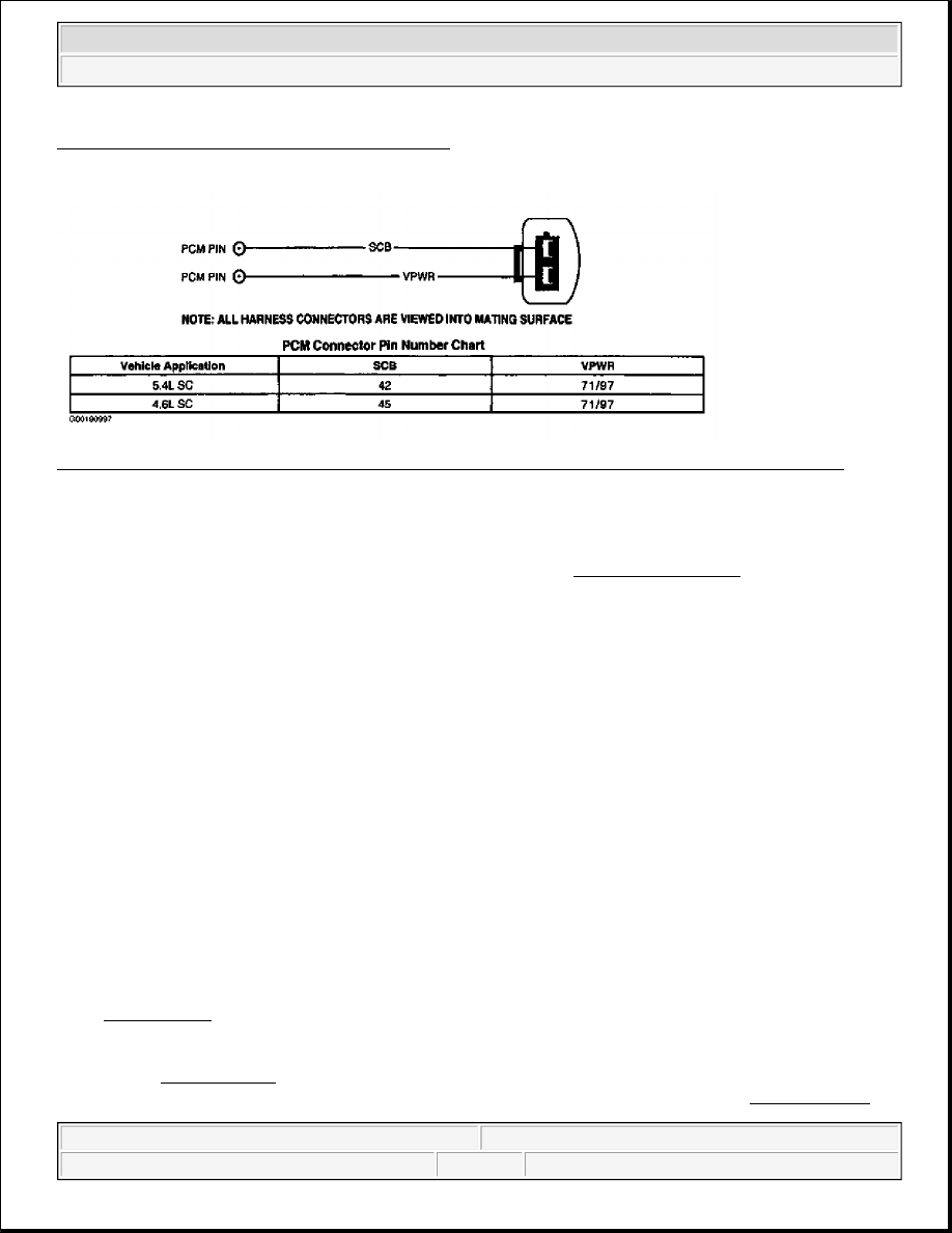
Fig. 334: Supercharger System Vacuum Diagram
Courtesy of FORD MOTOR CO.
 

Fig. 335: Identifying Supercharger (Boost) By-Pass Solenoid Wiring Harness Connector Terminals 
Courtesy of FORD MOTOR CO. 

Testing 

1) KOEO, KOER & Continuous Memory DTC P0234: Check For Other DTCs 
DTC P0234 is set and PCM disables supercharger boost to keep from damaging engine or transmission 
during potentially harmful operating conditions. Possible causes are. 

z

Brake Torque Condition (Brake Pedal Applied & Throttle At Wide Open Position)  

z

Transmission Oil Temperature Exceeds Calibrated Threshold  

z

Engine Overheating  

z

Ignition Misfire Exceeding Calibrated Threshold  

z

Knock Sensor Failure Or Knock Detected  

z

Low Speed Fuel Pump Relay Not Switching  

If engine is a no-start, go to TEST A, step 1). If engine starts and then stalls, diagnose by symptom. Go to 
SYMPTOMS in TROUBLE SHOOTING - NO CODES - CNG, FLEX-FUEL & GASOLINE article. If 
engine starts and does not stall, road test vehicle 10-15 minutes with engine speed exceeding 2000 RPM. 
Ensure engine is at normal operating temperature and that upper radiator hose is hot and pressurized. 
Repeat QUICK TEST and check for KOEO, KOER and Continuous Memory DTCs. If any other DTCs 
are present with DTC P0234, service other DTCs before continuing with this test. See DIAGNOSTIC 
TROUBLE CODE DEFINITIONS
. If only DTC P0234 is present, go to next step. 

NOTE:

For additional testing information, see DIAGNOSTIC AIDS.

NOTE:

Supercharger is by-passed when brakes are applied and throttle is in wide 
open position. This condition causes excessive engine torque and is 
referred to as brake torque. If possible, check with vehicle owner to 
determine if engine has been subjected to a brake torque condition 
causing DTC P0234 to set.


2003 Ford Pickup F150 

2003 ENGINE PERFORMANCE Self-Diagnostics - CNG, Flex-Fuel & Gasoline


2) Check Scan Tool PIDs For Causes Of Overboost Condition 
 
Start engine and allow to idle. Using scan tool, access IAT2, TFT and RPM PIDs from PID/DATA 
MONITOR & RECORD menu. If IAT2 PID value is more than 230°F (110°C), check for low fluid level 
in intercooler system. Check for cracked intercooler lines. Repair as necessary. If TFT PID value (5.4L 
SC only) is more than 275°F (135°C), check for low transmission fluid level. Check for transmission 
leaks. Repair as necessary. If IAT2 PID value is 230°F (110°C) or less and TFT PID value is 275°F (135°
C) or less, go to next step. 

3) Check For Low Speed Fuel Pump Relay Not Switching 
 
Start engine and allow to idle. Using scan tool, access LFPF PID from PID/DATA MONITOR & 
RECORD menu. If LFPF PID value indicates YES (fault present), go to TEST KA, step 45) and/or 60) 
and perform diagnostics for DTC P1232. If LFPF PID value indicates NO (no fault present), cause of 
overboost condition is unable to be determined at this time. Check for engine knock while driving 
vehicle. Repair as necessary. If engine knock is not present, ensure vehicle owner has an understanding of 
a brake torque condition and that brake torque can result in transmission damage. 

6) For KOEO, KOER & Continuous Memory DTC P0243: Check Supercharger (Boost) By-Pass 
Solenoid Output 
DTC P0243 is set when PCM detects Supercharger By-pass (SCB) solenoid circuit signal exceeds 
minimum or maximum allowable calibrated parameters for a specified SCB solenoid duty cycle (100 
percent or zero percent). Possible causes are: 

z

VPWR Circuit Open To SCB Solenoid  

z

SCB Solenoid Circuit Open, Or Shorted To PWR GND Or CHASSIS GND, Or VPWR  

z

Faulty SCB solenoid  

z

Faulty PCM  

Turn ignition switch to OFF position. Connect scan tool to Data Link Connector (DLC). Disconnect SCB 
solenoid connector. Connect a test light between SCB and VPWR circuits at SCB solenoid harness 
connector. See Fig. 335. Turn ignition switch to ON position. Using scan tool, access OUTPUT TEST 
MODE. See OUTPUT TEST MODE under ADDITIONAL SYSTEM FUNCTIONS. Attempt to close 
and open SCB solenoid driver in PCM by commanding ALL OUTPUTS ON and then OFF. Observe test 
light while cycling ALL OUTPUTS ON, then OFF. If test light illuminates then turns off, go to next step. 
If test light remains off, go to step 8). If test light remains illuminated, go to step 11). 

7) Check SCB Solenoid Resistance 
 
Turn ignition switch to OFF position. Using a DVOM, measure resistance between SCB solenoid 
terminals. If resistance is not 68-78 ohms, replace SCB solenoid. If resistance is 68-78 ohms, check for 

NOTE:

A break in step numbering sequence occurs at this point. Procedure skips 
from step 3) to step 6). No test procedures have been omitted.

NOTE:

For additional testing information, see DIAGNOSTIC AIDS.


2003 Ford Pickup F150 

2003 ENGINE PERFORMANCE Self-Diagnostics - CNG, Flex-Fuel & Gasoline


damaged vacuum hoses between intake manifold and SCB solenoid. Check for vacuum reservoir leaks. 
Repair or replace as necessary. If no faults are found, check for intermittent faults. Go to TEST Z, step 1). 

8) Check For Open VPWR Circuit Between SCB Solenoid & PCM Power Relay 
 
Using a DVOM, measure voltage between negative battery terminal and SCB solenoid harness connector 
VPWR terminal. See Fig. 335. If voltage is more than 10.5 volts, go to step 10). If voltage is 10.5 volts or 
less, go to next step. 

9) Check VPWR Circuit For Open In Harness 
 
Turn ignition switch to OFF position. Disconnect PCM connector. Inspect connector for loose, damaged 
or corroded terminals. Repair as necessary. Using a DVOM, measure resistance of VPWR circuit 
between PCM harness connector and SCB solenoid harness connector. See PCM CONNECTOR 
IDENTIFICATION
 and Fig. 335. If resistance is less than 5 ohms, go to next step. If resistance is 5 
ohms or more, repair open in VPWR circuit. 

10) Check SCB Circuit For Open In Harness 
 
Using a DVOM, measure resistance of SCB circuit between PCM harness connector and SCB solenoid 
harness connector. If resistance is less than 5 ohms, replace PCM. If resistance is 5 ohms or more, repair 
open in SCB circuit. 

11) Check SCB Circuit For Short To PWR GND In Harness 
 
Turn ignition switch to OFF position. Disconnect scan tool from DLC. Disconnect PCM connector. 
Inspect connector for loose, damaged or corroded terminals. Repair as necessary. Using a DVOM, 
measure resistance between SCB circuit and PWR GND circuits at PCM harness connector. See PCM 
CONNECTOR IDENTIFICATION
 and Fig. 335. See PCM PWR GND, SIG RTN & VREF 
TERMINAL IDENTIFICATION
 table. If all resistance measurements are more than 10 k/ohms, go to 
next step. If any resistance measurement is 10 k/ohms or less, repair short to PWR GND in SCB circuit. 
See WIRING DIAGRAMS

12) Check SCB Circuit For Short To PWR Or Chassis Ground In Harness 
 
Turn ignition switch to ON position. Using a DVOM, measure voltage between chassis ground and SCB 
circuit at PCM harness connector. If voltage is less than one volt, replace PCM. If voltage is one volt or 
more, repair SCB circuit for short to VPWR, VREF or chassis ground. See WIRING DIAGRAMS

13) Lack Of Power (Low Boost): Check Vacuum Hoses 
Check vacuum hoses for cracks, bends, kinks, leaks or being disconnected between the following areas: 

z

Supercharger by-pass actuator and supercharger by-pass solenoid. 

NOTE:

Step 13) is performed when directed here from LACK/LOSS OF POWER 
symptom under SYMPTOMS in TROUBLE SHOOTING - NO CODES - CNG, 
FLEX-FUEL & GASOLINE article.


2003 Ford Pickup F150 

2003 ENGINE PERFORMANCE Self-Diagnostics - CNG, Flex-Fuel & Gasoline


z

Supercharger by-pass solenoid and vacuum reservoir assembly.  

Repair or replace component(s) as necessary. If no concerns are found, return to LACK/LOSS OF 
POWER
 symptom diagnosis under SYMPTOMS in TROUBLE SHOOTING - NO CODES - CNG & 
GASOLINE article. 

TEST KL: SHIFT INDICATOR LIGHT 

Diagnostic Aids 

Perform this test only when directed here by a driveability symptom. This test is only intended to diagnose:  

z

Shift Indicator Light (SIL) Bulb & Instrument Cluster  

z

METER Fuse & VPWR Circuit To Instrument Cluster  

z

Wiring Harness Circuit; (SIL)  

z

Powertrain Control Module (PCM)  

NOTE:

SYSTEM TEST KL is performed when directed here from SYMPTOMS in 
TROUBLE SHOOTING - NO CODES - CNG, FLEX-FUEL & GASOLINE article.

NOTE:

This system test is for ZX2 M/T only.


2003 Ford Pickup F150 

2003 ENGINE PERFORMANCE Self-Diagnostics - CNG, Flex-Fuel & Gasoline


Content   ..  1566  1567  1568  1569   ..