Ford F150 Pickup. Instruction - part 1532


  Index      Ford     Ford F150 Pickup - service and repair instruction 2003 year


Search            copyright infringement  


Content   ..  1530  1531  1532  1533   ..


Ford F150 Pickup. Instruction - part 1532


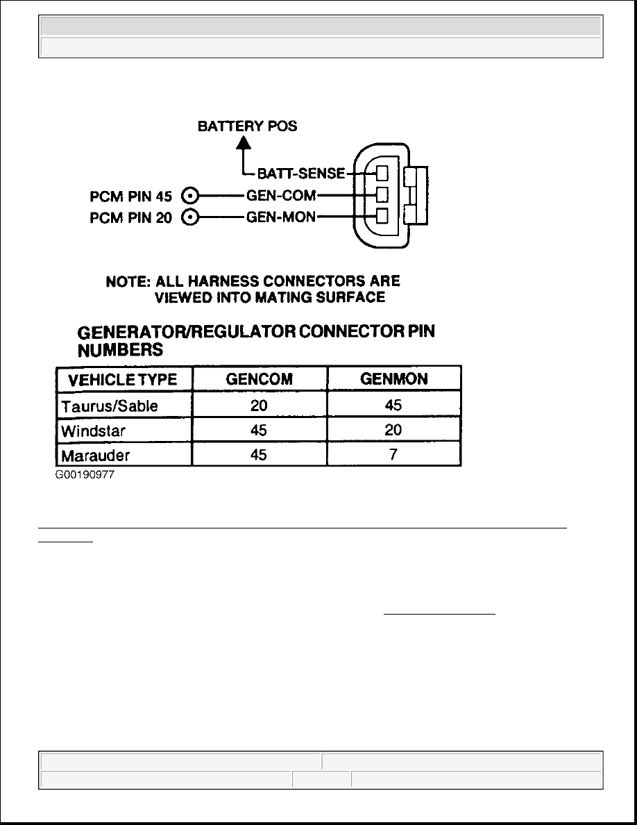
Fig. 278: Identifying Generator Wiring Harness Connector Terminals (Marauder, Sable, Taurus & 
Windstar)
 
Courtesy of FORD MOTOR CO. 

Testing 

1) For KOER & Continuous Memory Only DTCs P0622, P1244, P1245 & P1246: Verify Generator 
Drive Function 
The PCM monitors generator load from the generator/regulator in the form of frequency. The frequency 
range is determined by the temperature of the voltage regulator where 97 percent represents full load, 
below 6 percent means no load. Possible causes are: 

z

Generator circuit short to GND.  

z

Generator circuit short to PWR. 

NOTE:

For additional testing information, see DIAGNOSTIC AIDS.


2003 Ford Pickup F150 

2003 ENGINE PERFORMANCE Self-Diagnostics - CNG, Flex-Fuel & Gasoline


z

Generator circuit open.  

z

Generator drive mechanism.  

z

Damaged generator/regulator assembly.  

z

Damaged PCM.  

Check generator drive belt condition and tension. Start engine and verify generator is turning. Repair as 
necessary. See appropriate GENERATORS & REGULATORS article in STARTING & CHARGING 
SYSTEMS. If no faults are found, go to step 3) (for Expedition, Explorer, Mountaineer and Navigator) or 
go to next step (all others). 

2) Verify Charging System Is EEC Controlled 
 
Turn ignition switch to OFF position. Disconnect negative, then positive battery cable. Disconnect 
generator connector. Using a DVOM, measure resistance between BATT-SENSE and GEN-COM 
circuits at generator connector (except LS and Thunderbird). For LS and Thunderbird, measure resistance 
between GEN-MON and ground. See Fig. 275-Fig. 278 . If resistance is 950-1050 ohms (except LS and 
Thunderbird) or 53-203 ohms (LS and Thunderbird), go to next step. If resistance is not as specified, 
replace generator/regulator assembly. 

3) Check Battery Sense Voltage At Battery 
 
Reconnect generator connector. Reconnect battery cables to battery. Using a DVOM, measure voltage 
between battery terminals. Note voltage measurement. Using a DVOM, measure voltage between 
negative battery terminal and BATT-SENSE circuit at generator harness connector. If voltage is within .5 
volt (plus or minus) of battery voltage measurement, go to next step (for Expedition, Explorer, 
Mountaineer and Navigator), or go to step 5) (all others). If voltage is not within .5 volt of battery voltage 
measurement, repair BATT-SENSE circuit as necessary. 

4) Check EEC Control Circuit In PCM 
 
Turn ignition switch to OFF position. Disconnect generator and PCM harness connectors. Measure 
resistance between the I-Line and VPWR through the PCM where applicable for Expedition/Navigator. 
Measure resistance between the I-Line and ground through the PCM where applicable for 
Explorer/Mountaineer. If the resistances are within the ranges in the table, go to next step. See 
RESISTANCE VALUES FOR PCM CIRCUITS table. If the resistances are not within the ranges in 
the table, replace PCM. 

RESISTANCE VALUES FOR PCM CIRCUITS 

5) Check GEN-MON & GEN-COM Circuits For Short To PWR 
 
Turn ignition switch to OFF position. Disconnect PCM connector(s). Disconnect generator connector. 

Vehicle

Range (Ohms)

Expedition & Navigator

1550-1650

Explorer & Mountaineer

100-150


2003 Ford Pickup F150 

2003 ENGINE PERFORMANCE Self-Diagnostics - CNG, Flex-Fuel & Gasoline


Turn ignition switch to ON position. Using a DVOM, measure voltage between negative battery terminal 
and GEN-COM and GEN-MON circuits at PCM harness connector. See Fig. 275-Fig. 278 . If both 
voltage measurements are .5 volt or less, go to next step. If either voltage measurement is more than .5 
volt, repair short to PWR in affected circuit. 

6) Check GEN-COM & GEN-MON Circuits For Short To GND 
 
Turn ignition switch to OFF position. Using a DVOM, measure resistance between negative battery 
terminal and GEN-COM and GEN-MON circuits at PCM harness connector. If both resistance 
measurements are more than 10 k/ohms, go to next step. If either resistance measurement is 10 k/ohms or 
less, repair short to GND in affected circuit. 

7) Check GEN-COM & GEN-MON Circuits For Open 
 
Using a DVOM, measure resistance of GEN-COM and GEN-MON circuits between PCM harness 
connector and generator harness connector. If both resistance measurements are less than 5 ohms, go to 
next step. If either resistance measurement is 5 ohms or more, repair open in affected circuit. 

8) Check GEN-MON Signal 
 
Reconnect all connectors. Start engine and allow to idle. Using scan tool, access GFS PID from 
PID/DATA MONITOR & RECORD menu. If GFS PID (duty cycle) is 3-95 percent (for LS and 
Thunderbird) or 6-98 percent (all others), go to next step. If GFS PID (duty cycle) is not as specified, 
replace generator/regulator assembly. 

9) Check GEN-COM Signal 
 
With engine idling, access ARC (Expedition & Navigator) or GENFDC (all others) PID from PID/DATA 
MONITOR & RECORD menu. Observe ARC or GENFDC PID value, while cycling headlights on and 
off. If ARC or GENFDC PID duty cycle reading switched within zero to 99 percent, fault is unable to be 
duplicated at this time. Go to TEST Z, step 1). If ARC or GENFDC PID duty cycle reading did not 
switch within zero to 99 percent, replace PCM. 

10) Check Generator Charging Voltage 
Start engine and allow to idle. Using DVOM, measure battery voltage. If the battery voltage is 12.2-14.7 
volts, go to TEST Z, step 1). If the battery voltage is not 12.2-14.7 volts, replace generator/regulator 
assembly.  

TEST JB: SECONDARY IGNITION 

NOTE:

Explorer/Mountaineer do not have diagnostic PIDS, and LS/Thunderbird 
does not have a GENFDC PID.

NOTE:

After each service or repair procedure has been completed, reconnect all 
components. Clear DTCs and repeat QUICK TEST procedures to ensure all EEC-
V systems are working properly and DTCs are no longer present.


2003 Ford Pickup F150 

2003 ENGINE PERFORMANCE Self-Diagnostics - CNG, Flex-Fuel & Gasoline


Diagnostic Aids 

This test is intended to diagnose the following:  

z

Spark Plugs  

z

Spark Plug wires  

Fig. 279: Coil Pack Spark Diagram 
Courtesy of FORD MOTOR CO. 

NOTE:

A malfunctioning ignition system may cause high catalyst temperatures. Check 
components next to catalyst and muffler for heat damage.


2003 Ford Pickup F150 

2003 ENGINE PERFORMANCE Self-Diagnostics - CNG, Flex-Fuel & Gasoline


Content   ..  1530  1531  1532  1533   ..