Ford F150 Pickup. Instruction - part 1511


  Index      Ford     Ford F150 Pickup - service and repair instruction 2003 year


Search            copyright infringement  


Content   ..  1509  1510  1511  1512   ..


Ford F150 Pickup. Instruction - part 1511


Disconnect scan tool from DLC. Disconnect PCM connector(s). Inspect connector for loose, damaged or 
corroded terminals. Repair as necessary. Using a DVOM, measure resistance between negative battery 
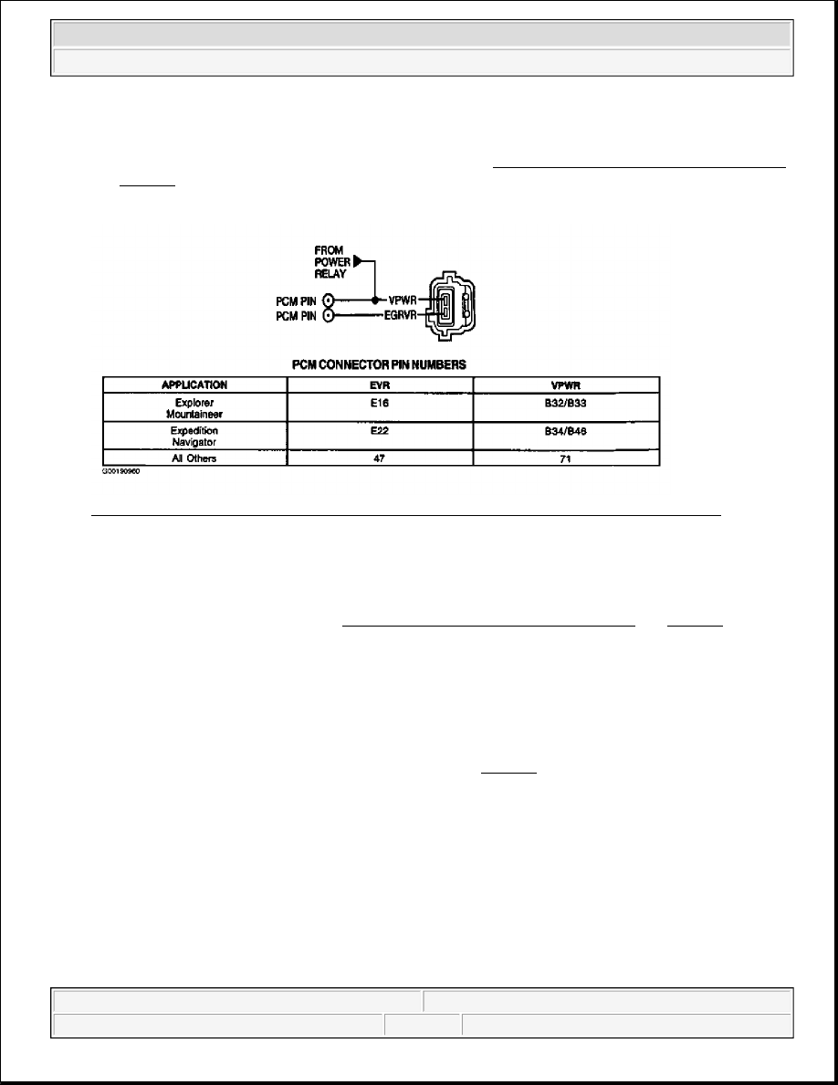
terminal and EGRVR circuit at PCM harness connector. See PCM CONNECTOR IDENTIFICATION
and Fig. 244. If resistance is more than 10 k/ohms, go to next step. If resistance is 10 k/ohms or less, 
repair short to ground in EGRVR circuit. 

Fig. 244: Identifying EGRVR Solenoid Wiring Harness Connector Terminals (All Others) 
Courtesy of FORD MOTOR CO. 

30) Check EGRVR Circuit For Short To VREF 
 
Using a DVOM, measure resistance between EGRVR and VREF circuits at PCM harness connector (both 
VREF circuits on 150-pin PCM). See PCM CONNECTOR IDENTIFICATION and Fig. 244. If 
resistance is more than 10 k/ohms, replace PCM. If resistance is 10 k/ohms or less, repair short between 
EGRVR and VREF circuits. 

31) Check DPFEGR Sensor Output By Applying Vacuum With Hand Pump 
 
Turn ignition switch to OFF position. Connect scan tool to Data Link Connector (DLC). Disconnect 
pressure hoses at DPFEGR sensor. Connect hand vacuum pump to downstream connection at DPFEGR 
sensor (intake manifold side or smaller diameter port). See Fig. 239. Using scan tool, access DPFEGR 
PID from PID/DATA MONITOR & RECORD menu. Read the following DPFEGR PID values with 
ignition switch in ON position: 

z

DO NOT apply vacuum to sensor. Record DPFEGR PID value. DPFEGR PID value should be .2-
1.3 volts.  

z

Using vacuum pump, apply 8-9 in. Hg (27-30 kPa) for a few seconds. DPFEGR PID value should 
increase to more than 4 volts.  

z

Quickly release vacuum. DPFEGR PID value should drop to less than 1.5 volts within 3 seconds of 
releasing vacuum.  

If any DPFEGR PID values are not as specified, replace DPFEGR sensor. If all DPFEGR PID values are 


2003 Ford Pickup F150 

2003 ENGINE PERFORMANCE Self-Diagnostics - CNG, Flex-Fuel & Gasoline


as specified, reconnect DPFEGR sensor and go to next step.

32) Check DPFEGR Sensor Voltage While Operating EGR Valve 
 
Ensure DPFEGR sensor is connected. Turn ignition switch to ON position. Using scan tool, access 
DPFEGR PID from PID/DATA MONITOR & RECORD menu. Record KOEO DPFEGR PID voltage 
reading. DPFEGR PID voltage reading should be .2-1.3 volts with no EGR flow. Disconnect and plug 
vacuum hose at EGR valve. Connect a hand vacuum pump to EGR valve. Start engine and allow to idle. 
Observe DPFEGR PID voltage reading at idle and compare to KOEO reading. Apply about 2-3 in. Hg (7-
10 kPa) of vacuum to open EGR valve without stalling engine, then release vacuum. Repeat several times 
while observing DPFEGR PID. DPFEGR PID voltage reading should increase as EGR valve begins to 
open, and return to initial voltage reading as vacuum is released. A higher voltage reading at idle 
indicates an EGR valve not seating fully. If DPFEGR PID is slow to return to initial voltage reading after 
releasing vacuum, EGR valve may be binding or slow closing. Service or replace EGR valve as 
necessary. If DPFEGR PID quickly returns to initial voltage reading after releasing vacuum, go to next 
step. 

33) Monitor EGR Valve Vacuum While Wiggling EGRVR Solenoid Circuit 
Turn ignition switch to OFF position. Remove hand vacuum pump from EGR valve vacuum hose. 
Connect a vacuum gauge to EGR valve vacuum hose. Start engine and allow to idle. Observe vacuum 
gauge for indication of fault while tapping lightly on EGRVR solenoid and wiggling EGRVR solenoid 
connector and wiring harness between PCM and solenoid to simulate road shock. Fault is indicated by a 
sudden jump in vacuum gauge reading. If no fault is indicated, reconnect vacuum hose to EGR valve and 
go to next step. If a fault is indicated, isolate and repair fault as necessary. 

34) Inspect EGRVR Solenoid & Vacuum Hoses For Potential Plugging 
Turn ignition switch to OFF position. Remove EGRVR solenoid vent filter. Inspect for contamination or 
water. Remove EGR vacuum hose and inspect for pinching or restriction. Repair or replace as necessary. 
If no faults are found, concern is intermittent and cannot be identified at this time. Go to TEST Z, step 1). 

NOTE:

An intermittent short to GND in EGRVR circuit may cause higher than 
normal vacuum to be applied to EGR valve. Normal vacuum to EGR valve 
at idle should be less than one in. Hg. EGR valve normally begins to open 
when applied vacuum is more than 1.6 in. Hg.

NOTE:

In colder climates, excessive water in vent filter may freeze and plug 
solenoid vent.

NOTE:

A break in step numbering sequence occurs at this point. Procedure skips 
from step 34) to step 50). No test procedures have been omitted.

NOTE:

For additional testing information, see DIAGNOSTIC AIDS.


2003 Ford Pickup F150 

2003 ENGINE PERFORMANCE Self-Diagnostics - CNG, Flex-Fuel & Gasoline


Fig. 245: Identifying DPFEGR Sensor Vacuum Circuits 
Courtesy of FORD MOTOR CO. 

50) For Continuous Memory Only DTC P1405: Check Upstream Pressure Hose Connections 
DTC P1405 indicates EGR MONITOR failed while driving due to PCM detecting signal from DPFEGR 
sensor EGR flow is in the negative direction. Possible causes for this fault are: 

z

Upstream Hose Is Disconnected  

z

Upstream Hose Is Plugged (Ice)  

z

Plugged Or Damaged EGR Tube  

Check upstream hose at DPFEGR sensor and orifice tube for clean and tight connections. See Fig. 245
Repair as necessary. Perform DRIVE CYCLES. Ensure EGR MONITOR PROCEDURE is performed to 
verify repair. If upstream hose connections are okay, go to next step. 

51) Inspect Upstream Pressure Hose For Plugging 
Check upstream hose for proper routing. Remove upstream hose and ensure it is not pinched and that 
hose routing does not have low spots where water could collect, freeze and plug hose in colder climates. 

NOTE:

Ensure DPFEGR pressure hose is the correct repair part and not a 
substitute.


2003 Ford Pickup F150 

2003 ENGINE PERFORMANCE Self-Diagnostics - CNG, Flex-Fuel & Gasoline


Repair as necessary. Perform DRIVE CYCLES. Ensure EGR MONITOR PROCEDURE is performed to 
verify repair. If upstream hose is okay, go to next step. 

52) Check Orifice Tube Assembly & DPFEGR Sensor 
 
Check DPFEGR sensor upstream connection on DPFEGR sensor for plugging or damage. See Fig. 245
Inspect exhaust manifold side pressure pick-up tube at orifice tube assembly for plugging or damage. 
Repair or replace DPFEGR sensor or orifice tube as necessary. Perform DRIVE CYCLES. Ensure EGR 
MONITOR PROCEDURE is performed to verify repair. If no faults are found, go to next step. 

53) Check DPFEGR Sensor Output By Applying Vacuum With Hand Pump 
 
Turn ignition switch to OFF position. Connect scan tool to Data Link Connector (DLC). Disconnect 
pressure hoses at DPFEGR sensor. Connect hand vacuum pump to downstream connection at DPFEGR 
sensor (intake manifold side or smaller diameter port). See Fig. 239. Using scan tool, access DPFEGR 
PID from PID/DATA MONITOR & RECORD menu. Read the following DPFEGR PID values with 
ignition switch in ON position: 

z

DO NOT apply vacuum to sensor. Record DPFEGR PID value. DPFEGR PID value should be .2-
1.3 volts.  

z

Using vacuum pump, apply 8-9 in. Hg (27-30 kPa) for a few seconds. DPFEGR PID value should 
increase to more than 4 volts.  

z

Quickly release vacuum. DPFEGR PID value should drop to less than 1.5 volts within 3 seconds of 
releasing vacuum.  

If any DPFEGR PID values are not as specified, replace DPFEGR sensor. If all DPFEGR PID values are 
as specified, reconnect DPFEGR sensor. Unable to duplicate or identify fault at this time, go to TEST Z, 
step 1). 

60) For Continuous Memory Only DTC P1406: Check Downstream Pressure Hose Connections 
If DTC P1406 is currently present, DTC P1408 will be output in KOER self-test. DTC P1406 indicates 
EGR MONITOR failed while driving when DPFEGR sensor continues to indicate EGR flow after EGR 
valve is commanded closed. Possible causes for this fault are: 

z

Downstream Hose Is Disconnected  

z

Downstream Hose Is Plugged (Ice)  

z

Plugged Or Damaged EGR Tube  

Verify EGR valve is securely attached and exhaust gasses are not leaking from the sealing surface. 

Check downstream hose at DPFEGR sensor and orifice tube for clean and tight connections. See Fig. 
245
. Repair as necessary. Perform DRIVE CYCLES. Ensure EGR MONITOR PROCEDURE is 

NOTE:

A break in step numbering sequence occurs at this point. Procedure skips 
from step 53) to step 60). No test procedures have been omitted.

NOTE:

For additional testing information, see DIAGNOSTIC AIDS.


2003 Ford Pickup F150 

2003 ENGINE PERFORMANCE Self-Diagnostics - CNG, Flex-Fuel & Gasoline


Content   ..  1509  1510  1511  1512   ..