Ford F150 Pickup. Instruction - part 1506


  Index      Ford     Ford F150 Pickup - service and repair instruction 2003 year


Search            copyright infringement  


Content   ..  1504  1505  1506  1507   ..


Ford F150 Pickup. Instruction - part 1506


Connect scan tool to Data Link Connector (DLC). Place gearshift lever in "P" position. Start engine and 
allow to idle. Using scan tool, access TANKPR PID from NGVM PID/DATA MONITOR & RECORD 
menu. Record TANKPR PID value. Using scan tool, access FRP PID from PCM PID/DATA MONITOR 
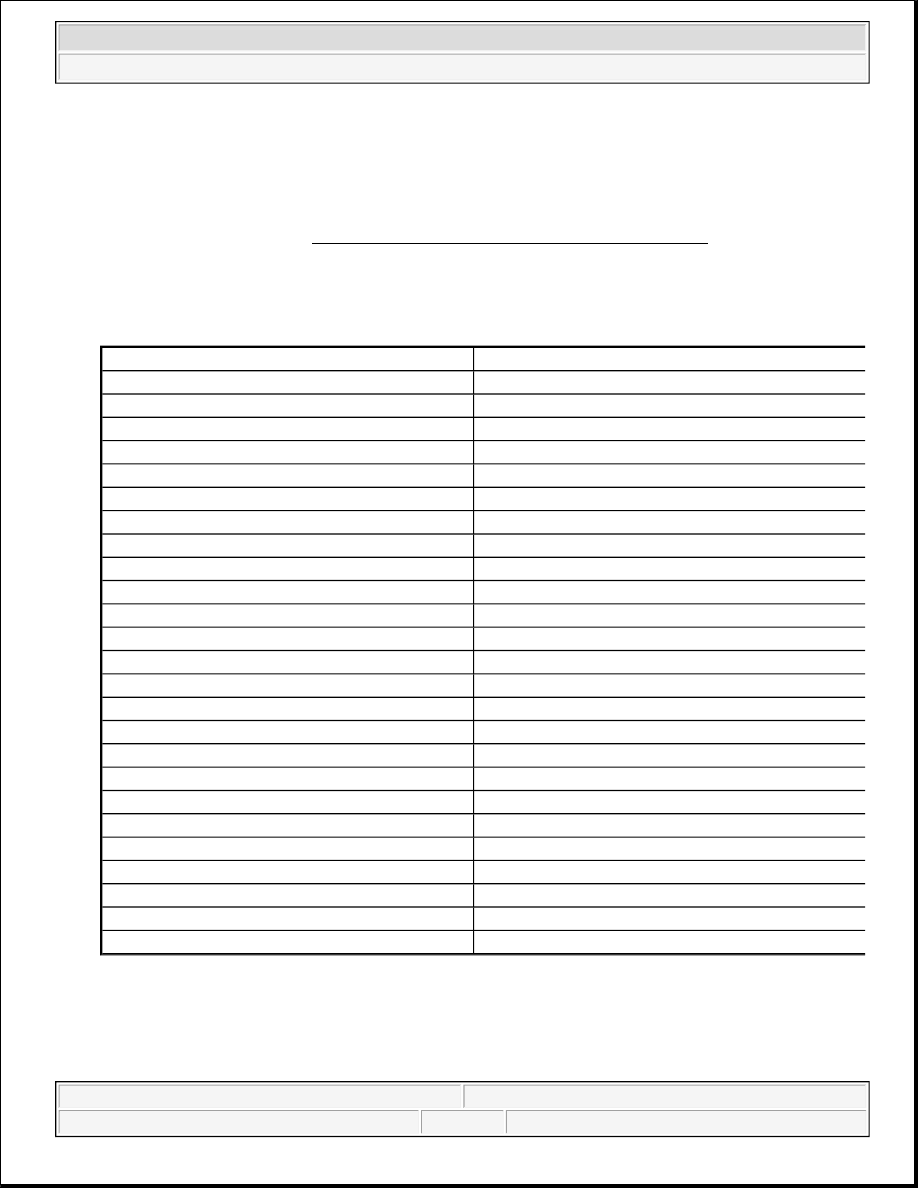
& RECORD menu. Record FRP PID value. Locate approximate TANKPR PID value and determine 
PCM inferred pressure using PCM INFERRED PRESSURE SPECIFICATIONS table. If PCM 
inferred pressure is plus or minus 22 psi of FRP PID value, no concern is indicated at this time. Service 
any other DTCs that are present. If PCM inferred pressure is not plus or minus 22 psi of FRP PID value, 
go to next step (for DTC P1180), or replace fuel pressure regulator (for DTC P1181). 

PCM INFERRED PRESSURE SPECIFICATIONS 

19) Check Fuel Filter For Water Or Other Contamination 
 
Disassemble fuel filter and check for water or any other contamination. If contamination is present, clean 
contaminants from filter housing and replace filter. If no contamination is present, go to next step. 

TANKPR PID Value - kPa

PCM Inferred Pressure - psi

2000

109

3000

108.4

4000

106.9

5000

106.5

6000

106

7000

105.6

8000

105

9000

104.5

10,000

103.4

11,000

103

12,000

102.5

13,000

102.3

14,000

101.8

16,000

100.8

17,000

99.8

18,000

99.3

19,000

99

20,000

98.5

21,000

97.5

22,000

97.3

23,000

96.3

24,000

96

26,000

96

28,000

95.5

30,000

94


2003 Ford Pickup F150 

2003 ENGINE PERFORMANCE Self-Diagnostics - CNG, Flex-Fuel & Gasoline


20) Check Fuel Line For Restriction 
 
Visually inspect all fuel lines for damage which may lead to restrictions and leakage. Repair as necessary. 
If all fuel lines are okay, go to next step. 

21) Determine Cause Of No Start 
 
Disconnect FRP Sensor electrical connector. Attempt to start vehicle. If engine will now start and run, 
replace fuel rail pressure sensor. If engine will not start and run, replace fuel pressure regulator.  

TEST HC: GASOLINE FUEL DELIVERY SYSTEM 

Diagnostic Aids 

Perform this test when directed by QUICK TEST or if directed by other test procedures. This test is used to 
diagnose:  

z

Chassis Components  

z

Engine Vacuum Systems  

z

Fuel Pressure  

z

Fuel Filter  

z

Fuel Return  

z

Fuel Supply  

z

Fuel Injector  

Testing 

1) For Continuous Memory Only DTC P0148: Check System Integrity 
This DTC indicates at least one bank lean at wide open throttle. Possible causes are: 

z

Severely restricted fuel filter.  

z

Severely restricted fuel supply line. 

NOTE:

After each service or repair procedure has been completed, reconnect all 
components. Clear DTCs and repeat QUICK TEST procedures to ensure all EEC-
V systems are working properly and DTCs are no longer present.

NOTE:

For specific vehicle fuel system identification, see Fig. 167.

WARNING:

Always refer to safety procedures to reduce possibility of injury. See 
FUEL SYSTEM SAFETY PRECAUTIONS.

NOTE:

For additional testing information, see DIAGNOSTIC AIDS.


2003 Ford Pickup F150 

2003 ENGINE PERFORMANCE Self-Diagnostics - CNG, Flex-Fuel & Gasoline


Visually inspect complete fuel delivery system for damage. Check fuel lines, connections, relays, fuel 
tank, fuel pump, fuel pressure regulator, fuel pulse damper and fuel injector areas for leaks. Check for 
looseness, cracks, kinks, pinching, or abrasion caused by a collision or mishandling. Visually inspect 
electrical harness and connectors for loose pins, corrosion, abrasion, or other damage from collision or 
mishandling. Check electrical connectors for proper mating. Ensure customer has followed vehicle 
maintenance schedule. Ensure Inertia Fuel Shutoff (IFS) switch is reset. Ensure battery is fully charged 
(12.5 volts or more) and that fuses are okay. Ensure fuel level in tank is sufficient. Repair as necessary. If 
no faults are found, go to next step. 

2) Check Voltage At Fuel Pump Harness Connector 
 
Connect battery charger to battery. Ensure IFS is reset. If it is not reset, perform INERTIA FUEL 
SHUTOFF SWITCH RESET PROCEDURE
 under GASOLINE SYSTEM under FUEL SYSTEM 
SAFETY PRECAUTIONS. Connect scan tool to Data Link Connector (DLC). Disconnect fuel pump 
harness connector at fuel pump. Turn ignition switch to ON position. Connect DVOM between fuel pump 
PWR and GND circuits at fuel pump harness connector. See WIRING DIAGRAMS. Using scan tool, 
access OUTPUT TEST MODE. See 

OUTPUT TEST MODE

 under ADDITIONAL SYSTEM 

FUNCTIONS. Command fuel pump ON and monitor DVOM voltage. If voltage is more than 12.5 volts, 
turn ignition switch to OFF position, exit OUTPUT TEST MODE, reconnect fuel pump harness 
connector and go to next step. If voltage is 12.5 volts or less, go to TEST KB, step 70) (ERFS vehicles), 
or check for open or shorts in fuel pump PWR or GND circuits (all others). See Fig. 167

3) Check Fuel Filter For Proper Maintenance 
 
Check last time fuel filter was replaced. If fuel filter has been serviced regularly (within 30,000 miles), go 
to next step. If fuel filter has not been serviced regularly, replace fuel filter and go to next step. 

4) Check Fuel Pressure 
Turn ignition switch to OFF position. Release fuel system pressure. See FUEL SYSTEM PRESSURE 
RELEASE procedure under FUEL SYSTEMS in appropriate REMOVAL & INSTALLATION article. 
Install fuel pressure gauge supplied in Kit (134-00114) to Schrader valve located on fuel rail. Turn 
ignition switch to ON position. Using scan tool, access OUTPUT TEST MODE. See OUTPUT TEST 
MODE
 under ADDITIONAL SYSTEM FUNCTIONS. Command fuel pump ON. 

Record fuel pressure. Compare fuel pressure to specification. See Fig. 167. If fuel pressure is within 
specification on vehicles with returnable fuel system, go to next step. If fuel pressure is within 
specification on vehicles with ERFS, go to step 6). If fuel pressure is within specification on vehicles with 
MRFS, go to step 12). See Fig. 167. If fuel pressure is not within specification, proceed as follows:  

z

If fuel pressure is more than specified on vehicles with MRFS, replace fuel pressure regulator in 
fuel tank. Recheck fuel pressure.  

z

If fuel pressure is less than specified on vehicles with MRFS, go to step 6).  

WARNING:

Always refer to safety procedures to reduce possibility of injury. See 
FUEL SYSTEM SAFETY PRECAUTIONS.

NOTE:

When energized by scan tool, fuel pump will operate for only 8 seconds.


2003 Ford Pickup F150 

2003 ENGINE PERFORMANCE Self-Diagnostics - CNG, Flex-Fuel & Gasoline


z

If fuel pressure is more than specified on vehicles with ERFS, repeat QUICK TEST. Other DTCs 
should be present if fuel pressure concern exists.  

z

If fuel pressure is more than specified on all other vehicles with returnable fuel system, go to step 
10).  

z

If fuel pressure is less than specified on all other vehicles with ERFS and returnable fuel system, go 
to step 13).  

5) Check Fuel Pressure Leakdown 
With fuel pressure gauge supplied in Kit (134-00114) connected to Schrader valve located on fuel rail, 
turn ignition switch to ON position. Using scan tool, access OUTPUT TEST MODE. See OUTPUT 
TEST MODE
 under ADDITIONAL SYSTEM FUNCTIONS. Command fuel pump ON. Record 
maximum fuel pressure. Turn ignition switch to OFF position. If fuel pressure remains within 5 psi (34 
kPa) of maximum fuel pressure for one minute after fuel pump turns off, go to step 7). If fuel pressure 
does not remain within 5 psi (34 kPa) of maximum fuel pressure for one minute after fuel pump turns off, 
go to next step. 

6) Check Pressure Regulator & Pulse Damper Diaphragm 
 
With fuel pressure gauge supplied in Kit (134-00114) connected to Schrader valve located on fuel rail, 
start engine and allow to idle for 10 seconds. Turn ignition switch to OFF position and wait 10 seconds. 
Start engine again and allow to idle for 10 seconds. Turn ignition switch to OFF position. Disconnect and 
inspect vacuum hose from fuel pressure regulator or pulse damper. If hose is wet with fuel, replace pulse 
damper (vehicles with MRFS), or fuel pressure regulator (all others). If hose is dry, go to step 13) 
(vehicles with MRFS), or go to step 12) (all others). 

7) Check Fuel Pressure While Test Driving Vehicle 
 
Ensure fuel pressure gauge supplied in Kit (134-00114) is connected to Schrader valve located on fuel 
rail. Disconnect and plug fuel pressure regulator vacuum hose. Drive vehicle with heavy accelerations 
while monitoring fuel pressure gauge reading. If fuel pressure reading holds steady within 3 psi (21 kPa) 
during road test, go to next step. If fuel pressure reading does not hold steady within 3 psi (21 kPa) during 
road test, go to step 13). 

8) Check Fuel Pressure Regulator Response 
 
Ensure fuel pressure gauge supplied in Kit (134-00114) is connected to Schrader valve located on fuel 
rail. Install vacuum gauge to intake manifold. Ensure fuel pressure and vacuum gauges can be seen by 
vehicle operator. Road test vehicle, accelerating and decelerating engine speed while monitoring fuel 
pressure and vacuum gauge readings. Fuel pressure gauge reading should increase as vacuum gauge 
reading decreases, and decrease as vacuum gauge reading increases. If gauge readings do not operate as 
specified, go to next step. If gauge readings operate as specified, fuel system is functioning properly. 
Diagnose by symptom. See SYMPTOMS in TROUBLE SHOOTING - NO CODES - CNG, FLEX-
FUEL & GASOLINE. 

WARNING:

Always refer to safety procedures to reduce possibility of injury. See 
FUEL SYSTEM SAFETY PRECAUTIONS.


2003 Ford Pickup F150 

2003 ENGINE PERFORMANCE Self-Diagnostics - CNG, Flex-Fuel & Gasoline


Content   ..  1504  1505  1506  1507   ..