Ford F150 Pickup. Instruction - part 1499


  Index      Ford     Ford F150 Pickup - service and repair instruction 2003 year


Search            copyright infringement  


Content   ..  1497  1498  1499  1500   ..


Ford F150 Pickup. Instruction - part 1499


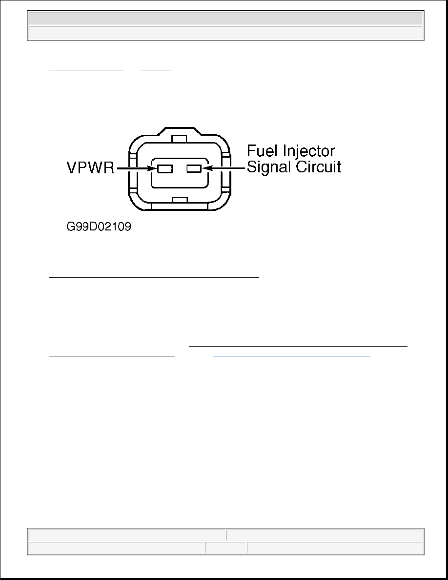
IDENTIFICATION and Fig. 234. If both resistance measurements are less than 5 ohms, go to next step. 
If either resistance measurement is 5 ohms or more, repair open in fuel injector signal or VPWR circuit. 

Fig. 234: Identifying Fuel Injector Connector Terminals 
Courtesy of FORD MOTOR CO. 

58) Check Fuel Injector Harness Circuit For Short To PWR Or GND 
 
Turn ignition switch to OFF position. Disconnect PCM harness connector(s). Ensure suspect fuel injector 
is disconnected. Using a DVOM, measure resistance between SIG circuit, and PWR GND and VPWR 
circuits at PCM harness connector. See PCM FUEL INJECTOR, PWR GND & VPWR CIRCUIT 
TERMINAL IDENTIFICATION
 table. See 

PCM CONNECTOR IDENTIFICATION

. If each 

resistance measurement is more than 10 k/ohms, go to next step. If either resistance measurement is 10 
k/ohms or less, repair short between circuits. 

59) Flow Test Fuel Injector(s) 
 
Turn ignition switch to OFF position. Reconnect PCM and fuel injector connector(s). Use Rotunda fuel 
injector tester from Fuel Tester Kit (113-00114) to flow test fuel injectors. Follow injector tester 
instructions. If fuel injector flow or leakage rate is not okay, replace defective fuel injector(s). If flow rate 
for each fuel injector is okay, proceed as follows: 

z

For DTCs P1131, P1151, P2195 and P2197, go to next step.  

z

For DTCs P0171 and P0174, go to step 61).  

z

For DTCs P1132, P1152, P2196 and P2198, go to step 64).  

z

For DTCs P0172 and P0175, fault is unable to be duplicated at this time. Go to TEST Z, step 1).  

NOTE:

If vehicle is not equipped with secondary air injection, go to next step.


2003 Ford Pickup F150 

2003 ENGINE PERFORMANCE Self-Diagnostics - CNG, Flex-Fuel & Gasoline


60) Check For Secondary Air Intrusion 
Possible causes for an HO2S always lean condition are: 

z

Leak In Hoses From Secondary Air Injection Pump  

z

Secondary Air Diverted Upstream Of HO2S  

Turn ignition switch to OFF position. Disconnect secondary air injection hoses from engine and plug 
engine side of air injection ports. Start engine and allow to reach operating temperature. Perform KOER 
ON-DEMAND SELF-TEST
. If DTC P1131, P1151, P2195 or P2197 is present, go to next step. If DTCs 
P1131, P1151, P2195 or P2197 are not present, check secondary air injection system. See TEST HM, step 
7). 

61) Check Air Induction System For Air Leaks 
 
Check inlet tubes from air cleaner to throttle body for leaks. Check PCV system for leaks. Check vacuum 
hoses for damage and tight connections. Check upper and lower intake manifold gaskets. If any faults are 
found, repair as necessary. If no faults are found, proceed as follows: 

z

For Continuous Memory DTCs P0171 or P0174, fault is unable to be duplicated at this time. Go to 
TEST Z, step 1).  

z

For DTCs P1131, P1151, P2195 and P2197, go to next step.  

62) Check Cylinder Compression 
 
Use Misfire DTCs retrieved in step 55) to determine which cylinder compression is suspect. Using 
compression gauge, check compression on all cylinders. Note suspect cylinder compression. Lowest 
cylinder compression should be more than 75 percent of highest cylinder compression reading. If suspect 
cylinder compression is not within specification, repair engine as necessary. If suspect cylinder 
compression is within specification, go to next step (if directed here for DTCs P1131, P1151, P2195 and 
P2197), or step 64) (if directed here for DTCs P1132, P1152, P2196 and P2198). If misfire DTCs are 
displayed with fuel control DTCs, go to TEST HD, step 20). 

63) Check HO2S Ability To Generate Voltage More Than .5 Volt 
 
Vacuum or air leaks can cause DTCs P1131, P1151, P2195, and P2197. Possible causes are: 

z

Water Contamination In Connector  

z

Leaking Vacuum Actuators  

z

Engine Sealing Concerns (Intake & IAC Valve)  

z

Faulty EGR Valve  

z

Faulty PCV System  

z

Unmetered Air Leaks Between Throttle Body & MAF Sensor  

Turn ignition switch to OFF position. Inspect HO2S wiring harness for chafing, burned wires or other 
damage. Repair as necessary. Disconnect suspect HO2S connector. Connect DVOM between HO2S SIG 
circuit, and SIG RTN or HO2S GND circuits at suspect HO2S connector. Start engine and operate at 
2000 RPM for 3 minutes. Perform KOER ON-DEMAND SELF-TEST while monitoring HO2S 


2003 Ford Pickup F150 

2003 ENGINE PERFORMANCE Self-Diagnostics - CNG, Flex-Fuel & Gasoline


voltage. If HO2S voltage increases to more than .5 volt, go to step 70). If voltage is .5 volt or less, replace 
faulty HO2S. 

64) Attempt To Generate DTC P1131, P1151, P2195 Or P2197 
 
Disconnect suspect HO2S connector. Connect a jumper wire between negative battery terminal and 
HO2S SIG circuit at suspect HO2S harness connector. Perform KOER ON-DEMAND SELF-TEST. If 
DTC P1131, P1151, P2195 or P2197 is present, turn ignition switch to OFF position, remove jumper wire 
and go to next step. If DTC P1131, P1151, P2195 or P2197 is not present, turn ignition switch to OFF 
position, remove jumper wire and reconnect HO2S harness connector. Disconnect and check PCM 
harness connector(s) for damaged or pushed out terminals, moisture or corrosion and repair as necessary. 
If PCM connector(s) is okay, replace PCM. 

65) HO2S Sensor Voltage Check 
 
Leave HO2S disconnected. Connect DVOM between HO2S SIG and SIG RTN circuits at suspect HO2S 
connector. Disconnect any vacuum hose from vacuum tree (simulates lean condition). Start engine and 
operate at 2000 RPM. If DVOM reads less than .4 volt within 30 seconds, turn ignition switch to OFF 
position, reconnect vacuum hose and HO2S and go to step 70). If DVOM reads .4 volt or more after 30 
seconds, replace HO2S and repeat KOER ON-DEMAND SELF-TEST. If DTCs P1132 or P1152 are 
still present, replace PCM. 

70) Monitor HO2S PID For Switching While Performing Wiggle Test 
Turn ignition switch to OFF position. Connect scan tool to Data Link Connector (DLC). Start engine and 
allow to idle. Ensure engine is at normal operating temperature. Using scan tool, access suspect HO2S 
PID (11, 12, 21 or 22) from PID/DATA MONITOR & RECORD menu. Monitor suspect HO2S PID 
while wiggling and bending small sections of wiring harness between suspect HO2S and PCM. 

If suspect HO2S PID voltage stops switching, isolate fault and repair as necessary. If suspect HO2S PID 
voltage switches, turn ignition switch to OFF position and go to next step. 

71) Monitor HO2S PID Switching During Test Drive 
 
This test step requires an assistant. Using scan tool, access LOOP PID and ensure vehicle is in closed-
loop before proceeding. Test drive vehicle in a manner consistent with Freeze Frame Data in an attempt 
to duplicate original concern. Using an assistant, observe suspect HO2S PID. If suspect HO2S PID 
voltage switches, system is okay at this time and testing is complete. If suspect HO2S PID voltage does 

NOTE:

A break in step numbering sequence occurs at this point. Procedure skips 
from step 65) to step 70). No test procedures have been omitted.

NOTE:

HO2S may be displayed as O2S on scan tool.

NOTE:

DO NOT compare HO2S switch rate from bank No. 1 to bank No. 2 as an 
indication of sensor's function. It is normal to have a variance in switch 
ratio from bank to bank.


2003 Ford Pickup F150 

2003 ENGINE PERFORMANCE Self-Diagnostics - CNG, Flex-Fuel & Gasoline


not switch, replace HO2S. 

80) For Continuous Memory Only DTCs P0136 & P0156: Monitor Downstream HO2S Output 
Voltage For Activity; KOER DTC P1137, P1138, P1157, P1158, P2270, P2271, P2272 & P2273: 
Indicate Lack Of HO2S Switching 
DTCs P0136 and P0156 indicate output voltage of downstream HO2S did not meet calibrated limits. 
DTCs P1137, P1138, P1157 or P1158 indicate PCM does not detect output of HO2S in a calibrated 
amount of time (lean condition). DTCs P2270, P2271, P2272 and P2273 indicate lack of output of HO2S, 
rich or lean, in a calibrated amount of time. DTCs P0136, P1137, P1138, P2270 and P2271 are for HO2S-
12. DTCs P0156, P1157, P1158, P2272 and P2273 are for HO2S-22. See Fig. 230-Fig. 232 . Possible 
causes are: 

z

Damaged Wiring Harness Or Connector  

z

Crossed Sensor Wires  

z

Exhaust System Leaks  

z

Contaminated Or Faulty HO2S  

Service any Continuous Memory ignition and Misfire DTCs before continuing. If no Continuous Memory 
ignition or Misfire DTCs are present, check for possible causes listed in this step. Repair as necessary. If 
no faults are found, go to next step (DTCs P0136 and P0156), or go to step 82) (all other DTCs). 

81) Check For KOER DTCs P1137, P1138, P1157 Or P1158 
 
Start engine, and operate at 2000 RPM for 3 minutes. Perform KOER ON-DEMAND SELF-TEST. If 
any combination of DTCs P1137, P1138, P1157, P1158, P2270, P2271, P2272 or P2273 is present along 
with P0136 or P0156, go to next step. If only DTC P0136 or P0156 is present, check for intermittent 
faults. Go to TEST Z, step 1). 

82) Check Exhaust System For Leaks 
Inspect exhaust system including catalytic converter and HO2S for the following: 

z

Incorrect HO2S Torque  

z

Exhaust System Leaks  

z

Punctures Or Cracks In Pipes Leading To Or In Catalytic Converter  

Repair as necessary. If exhaust system is okay, go to next step. 

83) Check HO2S SIG Circuit For Short To VPWR, VREF, SIG RTN Or PWR GND Circuits 

NOTE:

A break in step numbering sequence occurs at this point. Procedure skips 
from step 71) to step 80). No test procedures have been omitted.

NOTE:

For additional testing information, see DIAGNOSTIC AIDS.

NOTE:

DTCs P0136 and P0156 can be set when leaks exist in exhaust system 
between engine and rear of catalytic converter.


2003 Ford Pickup F150 

2003 ENGINE PERFORMANCE Self-Diagnostics - CNG, Flex-Fuel & Gasoline


Content   ..  1497  1498  1499  1500   ..