Ford F150 Pickup. Instruction - part 1342


  Index      Ford     Ford F150 Pickup - service and repair instruction 2003 year


Search            copyright infringement  


Content   ..  1340  1341  1342  1343   ..


Ford F150 Pickup. Instruction - part 1342


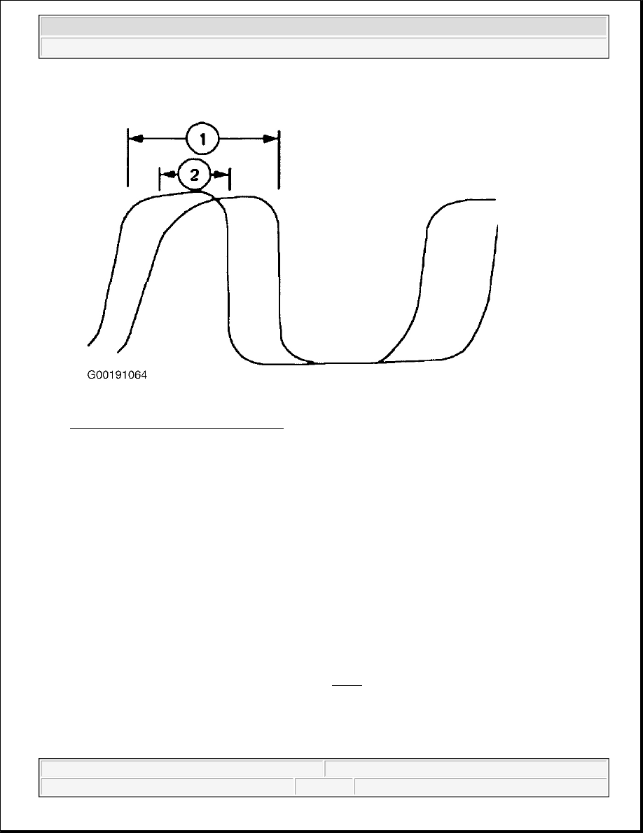
Fig. 4: Identifying HO2S Signal Display 
Courtesy of FORD MOTOR CO. 

11. Use an assistant in the driver seat to repeat step 6 . Obtain and hold the "tuning point" vacuum value.  

12. Select the NGS GRAPH option and record ten seconds of data from PCM PIDs O2S11 and O2S21. 

Allow the accelerator to return to the idle position and place the transmission in the Park position.  

13. Retrieve the recorded data and identify which of the OS2 signals displays the longest high state time as in 

step 10 .  

14. Determine which of the tuning tee adjustment screws requires adjustment. This is the only screw to be 

adjusted throughout the entire tuning tee procedure and is determined by the following: The PCM PID 
O2S11 data reflects the upstream bank 1 O2S and is adjusted with the passenger side tuning tee 
adjustment screw (1). The PCM PID O2S21 data reflects the upstream bank 2 O2S and is adjusted with 
the driver side tuning tee adjustment screw (2). See Fig. 3 . To reduce the PCM PID O2S11 or O2S21 
high state time the corresponding adjustment screw is turned clockwise and to increase the high state time 
the adjustment screw is turned counterclockwise.  

15. Turn the tuning tee adjustment screw identified in step 13 one complete turn clockwise and repeat steps 

10 through 12 .  

WARNING:

This step requires two people while the vehicle is running, in gear, 
and the engine accelerated. Be sure that the parking brake is fully 
set and the wheels are correctly chocked. Take all necessary 
precautions to avoid injury and property or equipment damage.


2003 Ford Pickup F150 

2003 ENGINE PERFORMANCE System & Component Testing - Bi-Fuel - Gasoline/LPG


16. Retrieve and compare the current graphed PCM PIDs O2S11 and O2S21 data with the previous data. If 

the determined PCM O2S PID from the previous graphed data continues to have the longer high state 
time, repeat steps 15 and this step.  

17. If the determined PCM O2S PID from the previous graphed data now has a shorter high state time, turn 

the corresponding tuning tee adjustment screw counterclockwise 1/2 turn and repeat steps 10 through 12 . 

18. Retrieve and compare the current recorded graphed PCM PIDs O2S11 and O2S21 data. If necessary, 

continue to turn the same adjustment screw by 1/4 and 1/8 turn increments clockwise or counterclockwise 
as described in step 

14

 repeating steps 10 through 12 with each adjustment until both O2S PIDs display 

equal high state time. See Fig. 5 . 

Fig. 5: Identifying HO2S Signal Display 
Courtesy of FORD MOTOR CO. 

19. When the retrieved PCM PIDs O2S11 and O2S21 data display equal high state time, the alternate fuel 

system is correctly tuned and no further adjustment is required. Document the following information: 
VIN, date, lead technician, assistant, O2S bank number adjusted, required number of turns to adjustment 
screw (to nearest 1/8th turn).  

20. Turn the ignition switch to the OFF position and remove the vacuum gauge and restore the intake vacuum 

system.  

21. Paint mark the tuning tee adjustment screw positions and seal the access hole with a manufacturers sensor 

safe sealant. Cover and label the adjustment screw cavities indicating that the alternative fuel system 
tuning procedure has been performed. Update all necessary vehicle inspection labels and placards. 


2003 Ford Pickup F150 

2003 ENGINE PERFORMANCE System & Component Testing - Bi-Fuel - Gasoline/LPG


2003 ENGINE PERFORMANCE

System & Component Testing - CNG 

INTRODUCTION 

ENGINE COVER 

Removal & Installation 

On models with console, open storage bin and press clips to remove storage bin. Press and hold lock clip and 
slide console up to remove. On all models, remove instrument panel cover under steering column. Disconnect 4 
engine cover latches and remove engine cover. To install, reverse removal procedure. 

COMPUTERIZED ENGINE CONTROLS 

POWERTRAIN CONTROL MODULE 

Ground Circuits 

Turn ignition off. Disconnect PCM 104-pin connector. See PCM LOCATION table. Using DVOM, check for 

NOTE:

References to Econoline include Cutaway and RV Cutaway models.

WARNING:

Before performing any tests or diagnostics on CNG or LPG components 
or systems, read all cautions and warnings in CNG/LPG SAFETY 
PRECAUTIONS article in GENERAL INFORMATION.

NOTE:

System and component testing included in this article is for CNG fuel systems 
only. For gasoline fuel system and component testing, see SYSTEM & 
COMPONENT TESTING - GASOLINE article. Since many computer-controlled 
and monitored components set a Diagnostic Trouble Code (DTC) when a 
malfunction occurs, check for Powertrain Control Module (PCM) DTCs prior to 
testing an individual system or component. Perform QUICK TEST procedures in 
SELF-DIAGNOSTICS - CNG, FLEX-FUEL & GASOLINE article. If no DTCs are 
present, perform SYMPTOM DIAGNOSIS under SYMPTOMS in TROUBLE 
SHOOTING - NO CODES - CNG, FLEX-FUEL & GASOLINE article to diagnose 
driveability problems existing when a hard fault code is not present.

NOTE:

Testing individual components does not isolate short or open circuits. Perform 
all voltage tests with a Digital Volt-Ohmmeter (DVOM) with a minimum 10-
megohm input impedance, unless stated otherwise in test procedure. Use 
DVOM to isolate shorted or open wiring harness. For identification of circuits 
and terminals referenced in test procedures, see ENGINE PERFORMANCE in 
appropriate SYSTEM WIRING DIAGRAMS article in ELECTRICAL.


2003 Ford Pickup F150 

2003 ENGINE PERFORMANCE System & Component Testing - CNG


2003 Ford Pickup F150 

2003 ENGINE PERFORMANCE System & Component Testing - CNG


continuity between chassis ground and specified PCM connector terminals. See IDENTIFYING PCM PWR 
GROUND TERMINALS
 table. See Fig. 1 or Fig. 2 . If continuity exists, see POWER CIRCUITS. If 
continuity does not exist, repair open in affected ground circuit. See ENGINE PERFORMANCE in appropriate 
SYSTEM WIRING DIAGRAMS article in ELECTRICAL. 

PCM LOCATION 

IDENTIFYING PCM PWR GROUND TERMINALS 

Power Circuits 

1. Turn ignition off. Using DVOM, check for battery voltage between chassis ground and PCM Keep Alive 

Memory Power (KAPWR) terminal No. 55. See Fig. 1 or Fig. 2 . If battery voltage is not present, check 
for open in KAPWR circuit or fuse battery junction box No. 12 (30-amp) on Crown Victoria, battery 
junction box fuse No. 4 (10-amp) on Econoline, or central junction box fuse No. 2 (5-amp) on F150 
Pickup. See ENGINE PERFORMANCE in appropriate SYSTEM WIRING DIAGRAMS article in 
ELECTRICAL. If battery voltage is present, go to next step.  

2. Turn ignition on. Using DVOM, check for battery voltage between chassis ground and VPWR at PCM 

connector terminals No. 71 (all models) and No. 97 (except Crown Victoria). If battery voltage is not 
present, power is not being supplied from PCM power relay. See TEST B: EEC-V POWER RELAY 
under SYSTEM TESTS in SELF-DIAGNOSTICS - CNG, FLEX-FUEL & GASOLINE article.  

Fig. 1: Identifying Powertrain Control Module Connector Terminals (Crown Victoria & Econoline) 
Courtesy of FORD MOTOR CO. 

Application

Location

Crown Victoria

Behind Left Kick Panel, Near Instrument Panel

Econoline

Left Rear Of Engine Compartment, Near Brake Master Cylinder

F150 Pickup

Right Rear Of Engine Compartment

Application

PCM Ground Terminal No.

Crown Victoria

3, 25, 51, 77 & 103

Econoline

3, 24, 25, 51, 76, 77 & 103

F150 Pickup

3, 25, 51, 76 & 103


2003 Ford Pickup F150 

2003 ENGINE PERFORMANCE System & Component Testing - CNG


Content   ..  1340  1341  1342  1343   ..