Ford F150 Pickup. Instruction - part 1290


  Index      Ford     Ford F150 Pickup - service and repair instruction 2003 year


Search            copyright infringement  


Content   ..  1288  1289  1290  1291   ..


Ford F150 Pickup. Instruction - part 1290


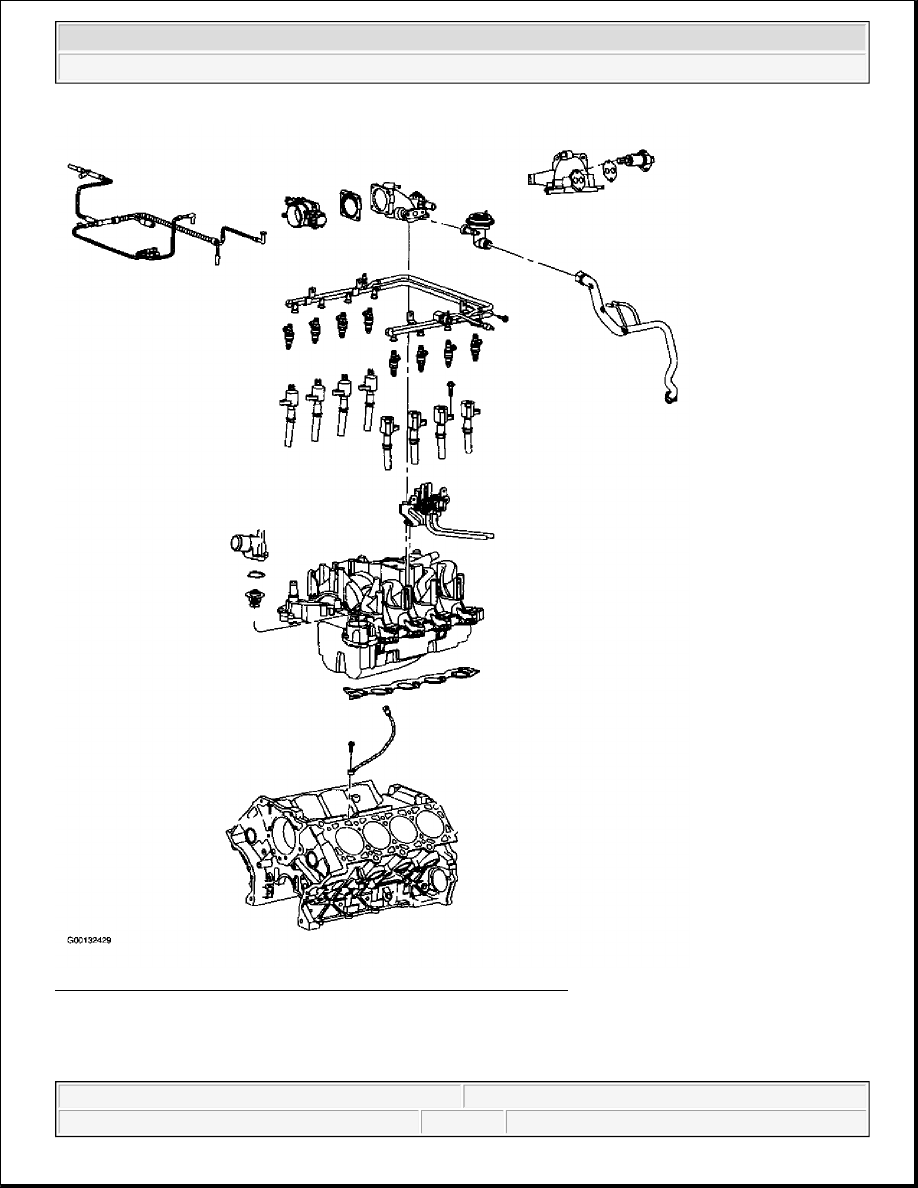
Fig. 28: Exploded View Of Intake Manifold Components (5.4L 2V) 
Courtesy of FORD MOTOR CO. 

Removal & Installation (5.4L 4V - Upper Intake Manifold) 


2003 Ford Pickup F150 

2003 ENGINE PERFORMANCE Removal & Installation - Blackwood, Expedition, F150 Pickup & Navigator - Gasoline


1. Disconnect the battery ground cable. Remove the cowl grille. Remove the bolts and five clips and the 

wiring harness shield. See Fig. 29 . Remove the air cleaner outlet tube. Disconnect the Mass Airflow 
(MAF) sensor electrical connector and remove the air cleaner assembly. Partially drain the cooling 
system. Remove the engine cover.  

2. Disconnect the accelerator cable, speed control cable, and the return spring. Remove the bolts and 

position the cables and bracket aside. See Fig. 30 . Disconnect Evaporative (EVAP) emission return line, 
Positive Crankcase Ventilation (PCV) tube and coolant lines. See Fig. 31 . Disconnect the electrical 
connector from the intake tuning valve. See Fig. 32 . Remove the bolts, stud and balance tube. See Fig. 
33
 .  

3. Use a plastic scraping tool to remove all traces of old sealant. Remove and discard the gaskets and clean 

the sealing surfaces. Disconnect the Throttle Position (TP) sensor. Disconnect the Idle Air Control (IAC) 
valve. Disconnect the vacuum lines and the electrical connector from the EGR Vacuum Regulator (EVR) 
valve. See Fig. 34 . Disconnect the two hoses and the electrical connector from the Differential Pressure 
Feedback EGR (DPFE). See Fig. 35 . Remove the EGR valve nut and bolts. Remove the bolts from 
power steering reservoir bracket, located at the front side of the left cylinder head and position aside. See 
Fig. 36 .  

4. Remove the stud and position the oil fill tube aside. Disconnect the brake booster vacuum line and other 

vacuum lines and position vacuum harness aside. Remove the bolts from the EGR adapter. See Fig. 37 . 
Remove and discard upper intake retaining bolts. Remove upper intake manifold and gaskets. 

5. Install the upper intake manifold gaskets. Position the upper intake manifold and loosely install NEW 

bolts. Tighten upper intake manifold bolts in sequence to specification. See Fig. 38 . See TORQUE 
SPECIFICATIONS
 . To complete installation, reverse removal procedure.  

CAUTION: Do not use metal scrapers, wire brushes, power abrasive discs or 

other abrasive means to clean the sealing surfaces. These tools 
cause scratches and gouges which make leak paths. Upper intake 
gasket may be reused, if undamaged. Upper intake manifold bolts 
must be replaced.


2003 Ford Pickup F150 

2003 ENGINE PERFORMANCE Removal & Installation - Blackwood, Expedition, F150 Pickup & Navigator - Gasoline


Fig. 29: Locating Wiring Harness Shield Retainers (5.4L 4V) 
Courtesy of FORD MOTOR CO. 


2003 Ford Pickup F150 

2003 ENGINE PERFORMANCE Removal & Installation - Blackwood, Expedition, F150 Pickup & Navigator - Gasoline


Fig. 30: Locating Accelerator Cable Bracket Bolts (5.4L 4V) 
Courtesy of FORD MOTOR CO. 


2003 Ford Pickup F150 

2003 ENGINE PERFORMANCE Removal & Installation - Blackwood, Expedition, F150 Pickup & Navigator - Gasoline


Content   ..  1288  1289  1290  1291   ..