Ford Fiesta (1989-1995). Instruction - part 45


  Index      Ford     Ford Fiesta - service and repair instruction 1989-1995 year


Search            copyright infringement  


Content   ..  43  44  45  46   ..


Ford Fiesta (1989-1995). Instruction - part 45


the equaliser from the primary cable (see
illustration)
.
Remove the primary cable guide by drifting
it out rearwards, through the floorpan, from
the inside of the vehicle.

Refitting

Refit in the reverse order of removal. Ensure
that the cable guide is secured in the floorpan,
and lubricate the pivot pin with a liberal
amount of high-melting-point grease.
Refit the exhaust system and heat shields
with reference to Chapter 4E (where applicable).
Refer to Chapter 1 for details, and adjust
the handbrake as required before lowering the
vehicle to the ground.

19 Handbrake rear cable -

removal and refitting

2

Removal

Chock the front wheels then jack up the
rear of the car and support it on axle stands
(see  “Jacking and Vehicle Support”). Fully
release the handbrake lever and remove the
rear roadwheels.
Refer to the previous Section for details,
and disconnect the handbrake primary cable
from the equaliser.
Disconnect the handbrake cable from its
adjuster body location and its fixed body

location (see illustration), then remove it from
its retaining clips.
Remove the rear brake drum(s) and brake
shoes as described in Sections 5 and 6
respectively.
Compress the handbrake cable retainer
lugs and release the cable from the backplate,
then pull the cable through. Release the cable
from the underbody fixings, and remove 
it from the vehicle.

Refitting

Refitting is a reversal of the removal
procedure. Refer to Sections 6 and 5
respectively for details on the refitting of the
brake shoes and drums.
When the cable is fully refitted (but before
lowering the vehicle rear wheels to the
ground) check and adjust the handbrake as
described in Chapter 1.

20 Brake pressure control

valves - removal and refitting

3

Note: Before starting work, refer to the
warning at the beginning of Section 13
concerning the dangers of hydraulic fluid.

Removal

The pressure control valves are located in
the engine compartment, fixed to the left-
hand inner wing panel or screwed directly into
the master cylinder fluid outlet ports (see
illustrations)
.
Minimise hydraulic fluid loss by
disconnecting the wiring multi-plug from the

fluid level warning indicator in the master
cylinder reservoir filler cap, then remove the
filler cap. Note that the filler cap must not be
inverted. Place a piece of plastic film over the
reservoir and seal it with an elastic band.
Detach the rigid brake pipes from the valves.
As the pipes are disconnected, tape over the
exposed ends, or fit plugs, to prevent the
ingress of dirt and excessive fluid loss.
To remove the inner wing panel mounted
assembly, remove the two screws securing
the valve assembly mounting bracket to the
inner wing panel, and withdraw the valve
assembly from the vehicle. To remove the
valves from the bracket, slide free the
retaining clips and detach the valve(s).
To remove the master cylinder mounted
valves, unscrew them from the master
cylinder body.

Refitting

Refitting is a reversal of the removal
procedure.
On completion, bleed the complete
hydraulic system as described in Section 13.

21 Light-laden valve (Courier

models) - removal and
refitting

3

Note: Before starting work, refer to the
warning at the beginning of Section 13
concerning the dangers of hydraulic fluid.

Removal

For this operation, the vehicle must be
raised for access underneath at the rear, but
must still be resting on its wheels. Suitable
ramps (or an inspection pit) will therefore be
required. If positioning the vehicle on a pair of
ramps, chock the front roadwheels.
Minimise hydraulic fluid loss by
disconnecting the wiring multi-plug from the
fluid level warning indicator in the master
cylinder reservoir filler cap, then remove the
filler cap. Note that the filler cap must not be
inverted. Place a piece of plastic film over the
reservoir and seal it with an elastic band.
Disconnect the four brake pipes from the
valve, and drain any escaping fluid into a
suitable container for disposal (see
illustration)
. Due to its location, care will be

Braking system  9•13

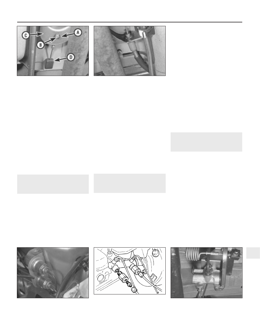
19.3  Handbrake rear cable fixed body

location

18.4  Handbrake equaliser yoke

arrangement

A Clevis pin securing clip
B Clevis pin
C Equaliser yoke
D Primary cable guide

21.3  Hydraulic pipe and linkage

attachments at the light-laden valve

20.1b  Pressure control valves and pipe

connections at the master cylinder - later

models

20.1a  Pressure control valves located on

left-hand inner wing panel

9

1595Ford Fiesta Remake

needed not to spill the fluid onto the hands -
wear suitable protective gloves. Plug or cap
the disconnected pipes and valve openings,
to prevent dirt ingress and further fluid loss.
Unbolt the valve from its mounting bracket,
unhook the linkage from the rear axle, then
withdraw the valve (see illustration). The
intermediate bracket may be unbolted if
required.

Refitting

Refitting is the reverse of the removal
procedure; adjust the valve as described in
Section 22, then bleed the complete hydraulic
system as described in Section 13. Check the
operation of the brakes before taking the
vehicle out on the road.

22 Light-laden valve (Courier

models) - adjustment

2

Note: To adjust the valve accurately, the
vehicle must be at a known rear axle loading -
owners who cannot determine the loading
with sufficient accuracy must have this check
made by a Ford dealer or similar expert.
For this operation, the vehicle must be
raised for access underneath at the rear, but
must be standing on its wheels. Suitable
ramps (or an inspection pit) will therefore be
required. If positioning the vehicle on a pair of
ramps, chock the front roadwheels.
Measure the distance between the inner
radius of the linkage’s hooked end and the
first shoulder (see illustration). If the
dimension is not as specified for the axle
loading, adjustment is required.
To adjust the setting, slacken the locknut
on the valve linkage, move the rod until the
setting is correct, then tighten the locknut
securely  (see illustration). Check the
operation of the brakes before taking the
vehicle out on the road.

23 Anti-lock braking system

(ABS) - general information

A mechanically-driven, two-channel anti-

lock braking system is available as a factory-
fitted option on certain model variants within
the Fiesta range.

The system comprises four main

components; two modulators, one for each
brake circuit, and two rear axle load-
apportioning valves, again, one for each brake
circuit. Apart from the additional hydraulic
piping, the remainder of the braking system is
the same as for conventional models.

The modulators are located in the engine

compartment with one mounted on each side
of the transmission, directly above the
driveshaft inner constant velocity joints. Each
modulator contains a shaft which actuates a
flywheel by means of a ball and ramp clutch.

A rubber toothed belt is used to drive the
modulator shaft from the driveshaft inner
constant velocity joint.

During driving and under normal braking

the modulator shaft and the flywheel rotate
together and at the same speed through the
engagement of a ball and ramp clutch. In this
condition hydraulic pressure from the master
cylinder passes to the modulators and then to
each brake in the conventional way. In the
event of a front wheel locking the modulator
shaft rotation will be less than that of the
flywheel and the flywheel will overrun the ball
and ramp clutch. This causes the flywheel to
slide on the modulator shaft, move inward and
operate a lever which in turn opens a dump
valve. Hydraulic pressure to the locked brake
is released via a de-boost piston allowing the
wheel to once again revolve. Fluid passed
through the dump valve is returned to the
master cylinder reservoir via the modulator
return hoses. At the same time hydraulic
pressure from the master cylinder causes a
pump piston to contact an eccentric cam on
the modulator shaft. The flywheel is then
decelerated at a controlled rate by the
flywheel friction clutch. When the speed of the
modulator shaft and flywheel are once again
equal the dump valve closes and the cycle
repeats. This complete operation takes place
many times a second until the vehicle stops or
the brakes are released.

The load-apportioning valves are mounted

on a common bracket attached to the rear
body, just above the rear axle twist beam
location, and are actuated by linkages
attached to the axle beam. The valves
regulate hydraulic pressure to the rear brakes,
in accordance with vehicle load and attitude,
so that the braking force available at the rear
brakes will always be lower than that available
at the front.

A belt-break warning switch is fitted to the

cover which surrounds each modulator
drivebelt. The switch contains an arm which is
in contact with the drivebelt at all times. If the
belt should break, or if the adjustment of 
the belt is too slack, the arm will move out
closing the switch contacts and informing the
driver via an instrument panel warning light.

24 Anti-lock braking system

(ABS) components - removal
and refitting

3

Modulator

Note: Before starting work, refer to the
warning at the beginning of Section 13
concerning the dangers of hydraulic fluid.
Disconnect the battery negative (earth) lead
(refer to Chapter 5A, Section 1).
Minimise hydraulic fluid loss by
disconnecting the wiring multi-plug from the
fluid level warning indicator in the master
cylinder reservoir filler cap, then remove the
filler cap. Note that the filler cap must not be
inverted. Place a piece of plastic film over the
reservoir and seal it with an elastic band.
Disconnect the modulator return hoses
from the master cylinder reservoir, collecting
any fluid spillage from the hoses in a suitable
tray. The modulator return hose unions should
be disconnected by first pushing the hose 
into the reservoir, then retaining the collar
against the reservoir body whilst withdrawing
the hose. Note that the hoses are colour
coded - the left-hand modulator has a black
return hose and connector, and should be
fitted to the forward section of the reservoir,
whilst the right-hand modulator has a grey
return hose and connector, and should be
fitted to the rear section of the reservoir.

9•14 Braking system

22.3  Light-laden valve linkage adjustment

locknut (arrowed)

22.2  Light-laden valve adjustment details

With rear axle load at 400 kg, 

“X” should be 147 mm

With rear axle load at 850 kg, 

“X” should be 166 mm

21.4  Light-laden valve mounting bolts

(arrowed)

1595Ford Fiesta Remake

Right-hand side

Chock the rear wheels then jack up the
front of the car and support it on axle stands
(see “Jacking and Vehicle Support”).
Remove the one-piece undertray where
fitted, by turning the bayonet type fasteners,
and on XR2i models, remove the front
suspension crossmember (see Chapter 10).
From underneath, remove the belt-break
switch from the right-hand drivebelt cover by
squeezing its release lever towards the main
body of the switch (see illustration), then
carefully withdraw, ensuring that the belt
contact arm does not catch on the drivebelt
cover.
Remove the two bolts securing the
modulator drivebelt cover to the modulator
mounting bracket, and withdraw the cover
(see illustration).
Disconnect the rigid brake pipes from the
modulator, fitting blanking plugs to prevent
excessive fluid loss and dirt ingress.
Remove the modulator pivot bolt and
adjuster bolt (see illustration), then slip the
drivebelt from its pulley, and withdraw the
modulator unit from the vehicle. Ensure that
the modulator return hose does not become
kinked as the modulator unit is withdrawn.
10 Disconnect the modulator return hose
from the modulator unit, and fit a blanking
plug to prevent dirt ingress. Allow for residual
fluid spillage as the hose is disconnected.
11 If a new modulator is to be fitted, note that
these units are not interchangeable from side
to side, and the correct replacement must be
obtained. The modulator units are colour-
coded, and must be fitted with the arrows on
top of the casings pointing towards the front
of the vehicle.
12 To refit, first connect the modulator return
hose to the return outlet on the modulator
unit.
13 Locate the modulator unit to its bracket
and fit the pivot bolt, having applied a thin
smear of anti-seize compound to the bolt, but
do not fully tighten at this stage. Take care not
to damage the modulator return hose as it is
manoeuvred into position.
14 Fit the drivebelt to its modulator pulley
location, ensuring that it sits correctly over the

driveshaft pulley, then refit the adjuster bolt
but do not fully tighten at this stage.
15 Adjust the tension of the drivebelt by
moving the modulator unit, until a belt
deflection of 5.0 mm is obtained under firm
finger pressure. Check this using a ruler at a
point midway between the two pulleys.
16 With the drivebelt tensioned correctly,
tighten the pivot and adjuster bolts to the
specified torque. Re-check the tension of the
drivebelt after tightening the bolts.
17 Reconnect the rigid brake pipes to the
modulator, tightening the unions securely.
18 Refit the modulator drivebelt cover to the
modulator mounting bracket, and secure with
its two retaining bolts.
19 Refit the belt-break switch to the
modulator drivebelt cover, taking care not to
damage the belt contact arm as it passes
through the cover.
20 Reconnect the modulator return hose by
pushing the hose firmly into its brake fluid
reservoir location, then lever out the collar to
retain it.
21 Refit the front suspension crossmember
and the one-piece undertray, as applicable.
22 Lower the vehicle to the ground.
23 Top-up the brake fluid reservoir using
fresh fluid of the specified type (see “Weekly
checks
”), then bleed the brake hydraulic
system in accordance with Section 14. Refit
the reservoir filler cap and warning indicator
wiring multi-plug on completion.
24 Reconnect the battery negative lead.

Left-hand side

25 Repeat the procedures given in
paragraphs 1 to 3.
26 Chock the rear wheels then jack up the
front of the car and support it on axle stands
(see “Jacking and Vehicle Support”). Remove
the front roadwheels.
27 Remove the one-piece undertray where
fitted, by turning the bayonet type fasteners,
and on XR2i models, remove the front
suspension crossmember (see Chapter 10).
28 Remove the belt-break switch from the
left-hand drivebelt cover in a similar manner to
that described in paragraph 6, this time from
the engine compartment.

29 Remove the two bolts securing the
modulator drivebelt cover to the modulator
mounting bracket, then ease the lower portion
of the cover over the driveshaft taking care
not to damage the driveshaft CV joint gaiter.
Withdraw the cover through the engine
compartment, manoeuvring it to clear
obstructions.
30 Disconnect the rigid brake pipes from the
modulator, fitting blanking plugs to prevent
excessive fluid loss and dirt ingress.
31 Slacken the modulator pivot and adjuster
bolts, then swing the modulator downwards
to release the drivebelt tension before slipping
the drivebelt from its modulator pulley
location.
32 Remove the modulator pivot and adjuster
bolts, withdraw the modulator upwards
through the engine compartment. Ensure that
the modulator return hose does not become
kinked as the modulator unit is withdrawn.
33 Disconnect the modulator return hose
from the modulator unit, and fit a blanking
plug to prevent dirt ingress. Allow for residual
fluid spillage as the hose is disconnected.
34 If a new modulator is to be fitted, note that
these units are not interchangeable from side
to side, and the correct replacement must be
obtained. The modulator units are colour-
coded, and must be fitted with the arrows on
top of the casings pointing towards the front
of the vehicle.
35 To refit, first connect the modulator return
hose to the return outlet on the modulator
unit.
36 Locate the modulator unit to its mounting
bracket and fit the pivot bolt, having applied a
thin smear of anti-seize compound to the bolt,
but do not fully tighten at this stage. Take care
not to damage the modulator return hose as it
is manoeuvred into position.
37 Fit the drivebelt to its modulator pulley
location, ensuring that it sits correctly over the
driveshaft pulley, then refit the adjuster bolt
but do not fully tighten at this stage.
38 Adjust the tension of the drivebelt by
moving the modulator unit, until a belt
deflection of 5.0 mm is obtained under firm
finger pressure. Check this using a ruler at a
point midway between the two pulleys.

Braking system  9•15

24.9  Modulator pivot bolt (A) and adjuster

bolt (B)

24.7  Modulator drivebelt cover to

mounting bracket securing bolts (arrowed)

24.6  Belt-break switch in drivebelt cover

A  Main switch body        B  Release lever

9

1595Ford Fiesta Remake

39 With the drivebelt tensioned correctly,
tighten the pivot and adjuster bolts to the
specified torque. Re-check the tension of the
drivebelt after tightening the bolts.
40 Reconnect the rigid brake pipes to the
modulator, tightening the unions to seal the
system.
41 Refit the modulator drivebelt cover and
secure with its two retaining bolts. Take care
not to damage the driveshaft CV joint gaiter as
the cover is eased into position.
42 Refit the belt-break switch to the
modulator drivebelt cover, taking care not to
damage the belt contact arm as it passes
through the cover.
43 Reconnect the modulator return hose by
pushing the hose firmly into its brake fluid
reservoir location, then lever out the collar to
retain it.
44 Refit the front suspension crossmember
and the one-piece undertray, as applicable.
45 Refit the roadwheels, then remove the
axle stands and lower the vehicle to the
ground. Tighten the wheel nuts to the
specified torque.
46 Top-up the brake fluid reservoir using
fresh fluid of the specified type (see “Weekly
checks
”), then bleed the brake hydraulic
system in accordance with Section 14. Refit
the reservoir filler cap and the warning
indicator wiring multi-plug on completion.
47 Reconnect the battery negative lead.

Modulator drivebelt

48 Disconnect the battery negative (earth)
lead (refer to Chapter 5A, Section 1).
49 Chock the rear wheels then jack up the
front of the car and support it on axle stands
(see “Jacking and Vehicle Support”). Remove
the relevant front roadwheel.
50 Remove the one-piece undertray where
fitted, by turning its bayonet-type fasteners,
and on XR2i models, remove the front
suspension crossmember (see Chapter 10).
51 Remove the belt-break switch from the
relevant drivebelt cover, then remove the
drivebelt cover, as described in the previous
sub-Section.
52 Slacken the modulator pivot and adjuster
bolts to release drivebelt tension, then slip the
drivebelt from the modulator.
53 Remove the track rod end balljoint from
the steering arm on the spindle carrier (see
Chapter 10).
54 Disconnect the anti-roll bar connecting
link (where applicable) and release the brake
hose from their locations on the suspension
strut.
55 Remove the pinch bolt and nut securing
the lower suspension arm balljoint to the
spindle carrier, and separate the balljoint from
the spindle carrier assembly.
56 To release the driveshaft inner CV joint
from the differential, have an assistant pull the
spindle carrier away from the centre of the
vehicle whilst you insert a lever between the
inner CV joint and the transmission casing,
then firmly strike the lever with the flat of the

hand, but be careful not to damage adjacent
components. Make provision for escaping
transmission oil, if possible plugging the
opening to prevent excessive loss. Do not
allow the CV joints to bend more than 20°
from the horizontal or internal damage may
occur. If both driveshafts are to be removed,
immobilise the differential by inserting an old
joint or suitable shaft, before the other
driveshaft is removed.
57 Slide the drivebelt off the driveshaft.
58 Remove the snap-ring from the groove in
the splines of the inner CV joint. This snap-
ring must be renewed every time the
driveshaft is withdrawn from the differential.
59 With the drivebelt removed, closely
examine the condition of the belt over its
entire length. Renew the belt if any cracks are
noticed in the fabric at the roots of the teeth, if
there is any abrasion of the fabric facing
material, or if there are any tears starting from
the edge of the belt.
60 If, since the drivebelts were last renewed,
a vehicle has covered more than 30 000 miles
(48 000 km) or a period of more than two
years has elapsed, the drivebelts should be
renewed as a matter of course.
61 Prior to refitting the drivebelt, thoroughly
clean its CV joint pulley location.
62 Fit the drivebelt over the driveshaft then,
with a new snap-ring fitted to the inner CV
joint splines, lubricate the splines with
transmission oil. Remove the temporary plug
and insert the inner CV joint to its
transmission casing location. Press against
the spindle carrier so that the snap-ring
engages fully to hold the CV joint splines in
the differential.
63 Refitting is now a reversal of the removal
procedure, tensioning the drivebelt as
described in the previous sub-Section. Ensure
that the pinch-bolt securing the lower
suspension arm balljoint to the spindle carrier
locates in the annular groove on the balljoint
spindle. Secure the track rod and balljoint,
using a new split pin. Tighten the suspension
components to their specified torque (see
Chapter 10).
64 Check the level of the transmission oil,
and top-up as required (see Chapter 1).

Modulator belt-break switch

65 Modulator belt-break switches are fitted
to each of the two drivebelt covers, and clip
into position. To remove, gently squeeze the
protruding lever on the switch towards the
main switch body and lift out, ensuring that
the belt contact arm does not catch on the
drivebelt cover.

25 Load-apportioning valve

(ABS models) - adjustment

3

Before attempting to adjust the load-
apportioning valves, the vehicle must be at its
kerb weight, ie with approximately half a tank
of fuel and carrying no load. Note that a
special setting tool will be required to adjust
the valves - this can be fabricated, to the
dimensions shown (see illustration).
Raise the vehicle on ramps or drive it over
an inspection pit, so that working clearance is
obtained with the full weight of the vehicle
resting on its roadwheels. Remove the spare
wheel and its carrier.
To check adjustment, insert the load-
apportioning valve setting tool into the nylon
sleeve without pre-loading the valve. If unable
to insert the tool, carry out the following
adjustment procedure.
Slacken the operating link adjustment fixing
screw then insert the setting tool into the
nylon sleeve, applying light pressure to the
operating link upper arm, so that the setting
tool fully locates. With the setting tool just
resting up against the adjustment post,
tighten the operating link adjustment fixing
screw to the specified torque (see
illustration)
.
Repeat the procedure on the other valve.
Refit the spare wheel on completion.

26 Load-apportioning valve

(ABS models) - removal and
refitting

3

Minimise hydraulic fluid loss by
disconnecting the wiring multi-plug from the
fluid level warning indicator in the master

9•16 Braking system

25.4  Load-apportioning valve adjustment

A Setting tool
B Operating link adjustment fixing screw
C Adjustment post

25.1  Load-apportioning valve adjustment

tool (dimensions given in mm)

1595Ford Fiesta Remake


Content   ..  43  44  45  46   ..