Dongfeng DFA1063DJ10 (14)-301/303. Manual - part 18


  Index      Dongfeng     Dongfeng DFA1063DJ10 (14)-301/303 - service manual 2006 year


Search            


Content   ..  16  17  18  19   ..


Dongfeng DFA1063DJ10 (14)-301/303. Manual - part 18


Rear Axle

RA-2

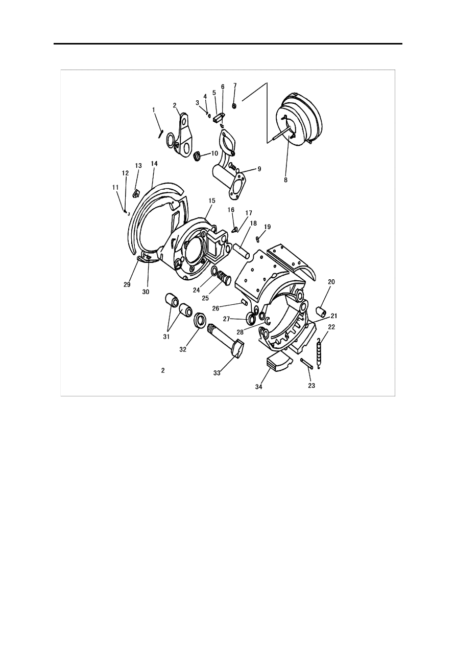
Disassembly of the brake

1.Cotter pin
2. Brake adjusting arm 
3.Cotter pin 
4.Plain washer
5.U-fork
6.Flat pin
7.Locking nut
8.Spring air chamber
9.Air chamber bracket 
10.Cam ring cage ring
11.Bolt 
12.Spring washer

13.Rubber plug 
14.Dustproof shield
15.Brake bottom plate
16.Set screw
17.Steel lock wire
18.Supporting pin
19.Rivet
20.Brake bush
21.Brake shoe
22.Return spring
23.Return spring pin
24.Spring washer

25.Screw
26.Roller pin shaft
27.Roller
28.Clamp ring
29.Dustproof shield
30.Grease nipple
31.Bush
32.Oil seal 
33.Cam shaft
34.Brake friction plate

Rear Axle

RA-3

Maintenance

Before using new axle, apply enough 2# lithium grease into every grease fitting.

First maintain

To assure the safe running of your vehicle and obtain a long service life, you have to do the first maintain

after the first 1,500~2,500kmafter leaving factory. Please note the following items:

1.Add or replace the gear oil for the reductor;

2.Dismantle and check the wheel hub brake drum assembly for any abnormal wear (please go to the Assembly

and Adjustment to see the reference)

3.Check the fastening piece.

Periodical maintain

Do the periodical maintain for the vehicle is a good way to prolong the service life and assure the safe run-

ning of the vehicle. If you follow the maintenance schedule to do the maintain, your vehicle may obtain the best
economic benefit.

The items of the periodical maintain are as following:

1.Add some grease to the grease nipple

2.Avoid important nut loosed

3.Adjust wheel hub bearing pretightening force and brake clearance

4.Add and replace the gear oil for the reductor

Periodical Maintain Schedule

Item

Maintenance Interval Mileage ( × 1000km)

First maintain

4

8

12 16 20 24 28 32 36 40 44 48 80

Clean the axle assy

● ● ● ● ● ● ● ● ● ● ● ●

Check main reductor for leakage

● ● ● ● ● ● ● ● ● ● ● ●

Replace grease of main reductor

Check lubricant level of the main 
reductor and clean the vent plug

Check tightness of the important 
bolts

● ● ● ● ● ● ● ●

Clean and adjust wheel hub bear-
ing

Do the magnetic particle test to 
half axle sleeve

Check service brake and parking 
brake efficiency

● ● ● ● ● ● ● ● ● ● ● ●

Check the tightness of the brake 
bottom plate

Clean brake air chamber

Check brake pipeline for leakage

● ● ● ● ● ● ● ● ● ● ● ●

Rear Axle

RA-4

Assembly and Adjustment

Disassemble and asseble of the assembly

Rear wheel hub brake drum assembly

1.Fixed the rear axle and remove the half axle bolt by a spanner;

2.Pull out the half axle gently and when the spline passing the oil seal, turn the half axle slowly to avoid damage

the half axle oil seal;

3.Take down three screws of the stop spacer by a screwdriver, then remove the stop spacer and dismantle the

adjusting nut by a spanner;

4.Turn the wheel hub brake drum a little and pull it, gently knock at the brake drum at the same time to loose the

inner ring of the outer bearing, then take down the wheel hub brake drum, but you need to pay attention that the
assembly is so heavy that may be fallen down or hurt someone, and the inner ring of the outer bearing need to
care at the same time, don't fall it.

The assembling sequence of the rear wheel hub brake drum assembly is opposite to the above sequence, and

you must to pay attention to the tightening torque of the thread connecting parts and the adjustment of the bearing
pretightening force.

Assembly of the main reductor assembly

1) Assembly of the drive gear

1.Press the outer ring of the front inner and outer bearing into the bearing seat;

2.Press the oil seal on the oil seal seat;

3.Press the inner ring of the front inner bearing onto the drive gear, and install the spacer sleeve, adjusting spacer,

bearing seat assembly and front outer bearing inner ring in sequence at the spline end of the gear;

4.Measure the pretightening load of the drive gear bearing: install the oil seal assembly, thrust washer, flange fork

and washer, then tighten the castle nut with a torque 350~500N.m and measure the pretightening force at this
time, the starting force of pulling the flange hole of the bearing seat should be 12~30N;

5.If the pretightening force is disqualified, you need to replace the adjusting spacer, reassemble to qualified;

6.Make use of a cotter pin to lock the castle nut.

2) Assembly of the differential

1.Install the bearing to the left and right differential housing;

2.Install planet gear, half axle gear, cross shaft, planet gear supporting washer, and half axle gear supporting

washer;

3.Measure the tooth space of the planet gear of the differential, check the clearance between half axle gear sup-

porting end face and the supporting washer with a clearance gauge, it should be ≤ 0.8 mm;

4.Align the marks of left and right differential housing and then assemble.

      Tightening torque: 140~160N.m

3) Assembly of the main reductor assembly

1.After assembled the bearing outer ring of the differential, install it onto the main reductor housing;

2.Install the adjusting nut and the bearing cover, then fasten with bolts;

3.Equably tighten the adjusting nut to pretighten the load until the pretightening load is between 16.4~24.3N;

4.Install the adjusting spacer of main cone to the bearing seat and assemble the drive conical gear assembly;

5.Adjust the gear tooth space to  0.20~0.40mm:

     The change value of the tooth space ≤ 0.15 mm

Rear Axle

RA-5

6.Paint two or three engaged teeth of driven gear red to chaeck the contact zone, if the contact area is improper,

increase or reduce the thickness of the adjusting spacer until it is proper;

Sketch map of the contact zone is as follows:

7.Tighten the bearing cover fixed bolt, reassemble the stop spacer.

Adjustment of the axle

Adjustment of the brake clearance

No matter if the brake clearance is too big or too small, it will effect the brake efficiency of the vehicle.

Please adjust the worm shaft hex-head of the adjusting arm by a spanner. Firstly, turn it with the clockwise until
you can't turn to make the clearance become zero, then turn with the counter clockwise until you hear two sounds
of steel ball, and the middle part clearance of the brake friction plate is 0.4~0.7mm.

Gear contact zone

Adjusting method

1

Proper contact zone

No need to adjust

2

The drive gear & the 
driven gear is too far

The drive gear and the driven 
gear is too far (reduce the 
thickness of the spacer)

3

The drive gear & the 
driven gear is too near

The drive gear and the driven 
gear is too near (increase the 
thickness of the spacer)

4

The contacting area of the 
driven taped gear is too 
low

The drive gear and the driven 
gear is too near (increase the 
thickness of the spacer)

5

The contacting area of the 
driven tapered gear is too 
high

The drive gear and the driven 
gear is too far (reduce the 
thickness of the spacer)


Content   ..  16  17  18  19   ..