Dongfeng DFA1101GZ5AD6J-907. Manual - part 29
 

  Index      Dongfeng     Dongfeng DFA1101GZ5AD6J-907 (Truck) - service manual 2006 year


Search            


Content   ..  27  28  29  30   ..


Dongfeng DFA1101GZ5AD6J-907. Manual - part 29


Clutch

CL-7

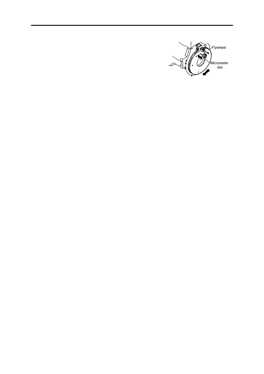
Flywheel check

Check the working face of the flywheel for ablation or color changed,

make use of the corundum paper to get rid of them if necessary.

Check the plainness of the flywheel surface: <0.1mm

Usage and Maintenance

The diaphragm clutch which has two positioning holes and been con-

nected by 8 M10 bolts,  is made up by cover assy and driven disc assy.

The drive blade is used to transmit the engine torque between the

pressure plate and clutch cover. Two ends of the drive blade are riveted to
the clutch cover and the pressure plate. When disengaged, the drive blade
may have the axial deformation, and there is no friction between clutch
cover and pressure plate. Therefore, the clutch will has a higher drive effi-
ciency, lower noise, and stable engage.

The working pressure force is caused by the diaphragm. The original

height of the clutch release finger is 56±1mm. During the usage, it will be
heigher because of wearing. The wear limit of the two pieces of the
friction lining is 2×1.8mm. During the wearing time, the distance between
the toppest point of the release finger and the release bearing end has to be
adjusted to 3~4mm, and the largest release stroke of the release finger is
10mm.

The outside diameter of the driven disc friction lining isΦ325mm. Its

material may adopt to asbestos or non-asbestos according to the need of
the customer. The original thickness of the driven disc working surface is
9.7±0.3mm. The assembly is equipped with big and small shock-absorber
spring and damping spacer which is good to absorb the impact and
vibration from the chassis.

The involute spline is used to connect the driven disc and

transmission.

The working surface of the driven disc can't be stained with oil soil

during the assembling and storage.

When the friction lining is in trouble, such as the rivet loose or come

out or cracked, the driven disc must be replaced immediately. 

During the assembling and instorage, the working surface of the

clutch cover assembly must haven't any scuffing and rust. If the release
finger is broken or the pressure plate reached to its wear limit and the
diaphragm is broken, you must replace the assembly immediately.

Clutch

CL-8

Transmission

MT

Table of Contents

Maintenance Standard ................................................................................... MT-1
Transmission Dismount................................................................................. MT-2
Transmission Disassembly ............................................................................ MT-3
Cleaning....................................................................................................... MT-20
Check ........................................................................................................... MT-20
Reassembly.................................................................................................. MT-24
Transmission Mount .................................................................................... MT-37

Transmission

MT-1

Maintenance Standard

Maintenance Standard

Item

Nominal 

Dimension

mm)

Sevice 

Standard

mm)

Repair 

Limit

mm)

Wear 

Limit

mm)

Remark

T

ransm

ission

 top 

cover

Clearance 
between gear 
shift lever and 
select lever

Gear shift lever

0.1~0.4

0.8

Gear select lever

Radial clearance between gear shift lever and 
its spline

0.05~0.11

0.5

Clearance 
between gear 
shift lever and 
guide block

Gear shift lever

0.1~0.4

1.0

Each guide block

T

ransmission

 up

per cov

er

Clearance between gear shift fork and slide 
sleeve

0.10~0.29

1.0

Gear shift fork 
shaft self-
locked spring

Free length

34.0~36.0

Pressure force

140~190

N

110N

When press to 

25mm

T

ransmi

ssi

on bod

y

Backlash between mainshaft and countershaft

0.15~0.25

0.5

Axial clearance of the 2nd gear

0.3~0.5

0.7

Axial clearance of the reverse gear

0.3~0.6

1.0

Radial clearance between mainshaft spline 
hub and mainshaft

0.2~0.3

0.5

Radial clearance between slide sleeve and 
coupling gear

0.45~0.55

1.0

Axial clearance of ball bearing

0.5

Synch

ron

izer

Lockpin type

Pretravel of synchronizer 
conical ring and conical disc

0~0.5

2.0

Slide block 
type

Clearance between baulk 
ring and synchronizer coni-
cal ring

1.5~2.5

0

Radial clearance between 
baulk ring and fixed tooth 
seat

5.3~5.7

Axial clearance between 
fixed seat and synchronizer 
closing ring

0.5

Axial clearance between 
fixed seat and synchronizer 
backing block

0.05~0.35

Free length of the backing 
block spring

15

Packing force of the back-
ing block spring

6~10N

4N

When press to 

12.5mm


Content   ..  27  28  29  30   ..