Dodge 2500 (2009 year). Manual - part 26


  Index      Dodge     Dodge 2500 (2009 year) - manual in english


Search            copyright infringement  


Content      ..     24      25      26      27     ..


Dodge 2500 (2009 year). Manual - part 26


• Operate the jack using the jack drive tube and the

wheel wrench. The tube extension, may be used, but
is not required.

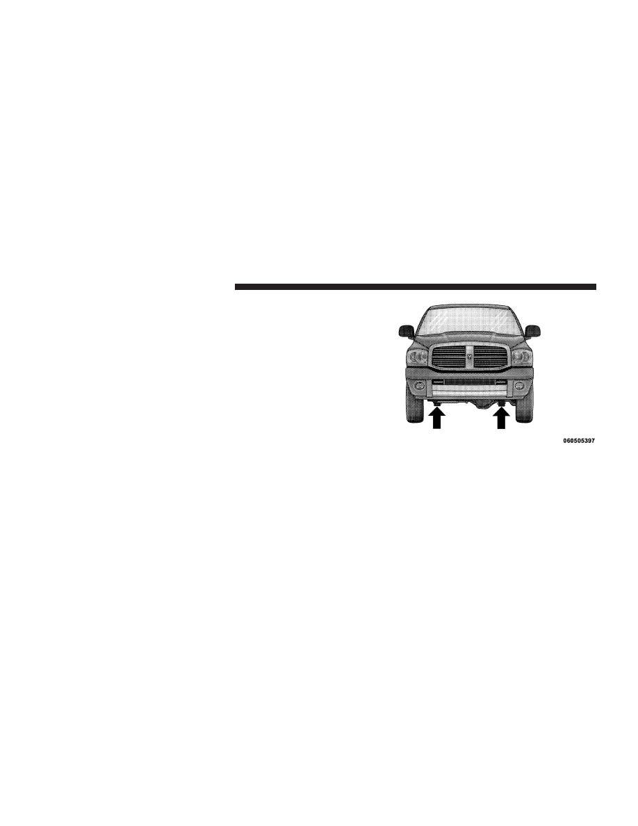
• For 2500/3500 4x4 series trucks, when changing the

front wheel, assemble the jack drive tube to the jack
and connect the drive tube to the extension tube.
Place the jack under the axle as close to the tire as
possible with the drive tubes extending to the front.
Connect the jack tube extension and wheel wrench.

• For all trucks, when changing a rear wheel, as-

semble the jack drive tube to the jack and connect
the drive tube to the extension tube. Place the jack
under the axle between the spring and the shock
absorber with the drive tubes extending to the rear.

4x4 Jacking Location

412

WHAT TO DO IN EMERGENCIES

• Connect the jack tube extension and wheel wrench.

Before raising the wheel off the ground, make sure
that the jack will not damage surrounding truck
parts and adjust the jack position as required.

NOTE:

If the 2500/3500 bottle jack will not lower by

turning the dial (thumbwheel) by hand, it may be neces-
sary to use the jack drive tube in order to lower the jack.

4. By rotating the wheel wrench clockwise, raise the
vehicle until the wheel just clears the surface.

WARNING!

Raising the vehicle higher than necessary can make
the vehicle unstable and cause an accident. It could
slip off the jack and hurt someone near it. Raise the
vehicle only enough to remove the tire.

5. Remove the wheel nuts and pull the wheel off. Install
the spare wheel and wheel nuts with the cone shaped end
of the nuts toward the wheel on 2500/3500 single rear-
wheel (SRW) models. On 3500 dual rear-wheel models
(DRW) the lug nuts are a two-piece assembly with a flat

Rear Jacking Location (All)

WHAT TO DO IN EMERGENCIES

413

6

face. Lightly tighten the nuts. To avoid risk of forcing the
vehicle off the jack, do not fully tighten the nuts until the
vehicle has been lowered.

6. Using the wheel wrench, finish tightening the nuts
using a crisscross pattern. The correct nut tightness is
135 ft lbs (183 N·m) torque for 2500/3500 single-rear
wheel (SRW) models, and 145 ft lbs (197 N·m) for 3500
dual rear-wheel models. If in doubt about the correct
tightness, have them checked with a torque wrench by
your authorized dealer or at a service station.

WARNING!

A loose tire or jack thrown forward in a collision or
hard stop could injure someone in the vehicle. Al-
ways stow the jack parts and the extra tire and wheel
in the places provided.

7. Install wheel center cap and remove wheel blocks. Do
not install chrome or aluminum wheel center caps on the
spare wheel. This may result in cap damage.

8. Lower the jack to its fully closed position. If the bottle
jack will not lower by turning the dial (thumbwheel) by
hand, it may be necessary to use the jack drive tube in
order to lower the jack. Stow the replaced tire, jack, and
tools as previously described.

9. Adjust the tire pressure when possible.

NOTE:

Do not oil wheel studs. For chrome wheels, do

not substitute with chrome plated wheel nuts.

Hub Caps/Wheel Covers
The hub caps must be removed before raising the vehicle
off the ground.

For 2500/3500 single rear-wheel (SRW) models, use the
blade on the end of the lug wrench to pry the hub cap off.

414

WHAT TO DO IN EMERGENCIES

Insert the blade end into the pry-off notch and carefully
pop off the hub cap with a back-and-forth motion.

On 3500 models with dual rear wheels (DRW), you must
first remove the hub caps. The jack handle driver has a
hook at one end that will fit in the pry off notch of the
rear hub caps. Position the hook and pull out on the
ratchet firmly. The hub cap should pop off. The wheel
skins can now be removed. For the front hub cap on 3500
models use the blade on the end of the lug wrench to pry
the caps off. The wheel skin can now be removed.

CAUTION!

• Use a back-and-forth motion to remove the hub

cap. Do not use a twisting motion when removing
the hub cap, damage to the hub cap finish may
occur.

(Continued)

CAUTION! (Continued)

• The rear hub caps on the dual rear wheel has two

pry-off notches. Make sure that the hook of the
jack handle driver is located squarely in the cap
notch before attempting to pull off.

You must use the flat end of the lug wrench to pry off the
wheel skins. Insert the flat tip completely and using a
back-and-forth motion, loosen the wheel skin. Repeat this
procedure around the tire until the skin pops off.

Replace the wheel skins first using a rubber mallet. When
replacing the hub caps, tilt the cap retainer over the
lugnut bolt circle and strike the high side down with a
rubber mallet. Be sure that the hub caps and wheel skins
are firmly seated around the wheel.

WHAT TO DO IN EMERGENCIES

415

6

8-Stud — Dual Rear Wheels
Dual wheels are flat-mounted and center-piloted. The lug
nuts are a two-piece assembly. When the tires are being
rotated or replaced, clean these lug nuts and add two
drops of oil at the interface between the hex and the
washer.

Slots in the wheels will assist in properly orienting the
inner and outer wheels. Align these slots when assem-
bling the wheels for best access to the tire valve on the
inner wheel. The tires of both dual wheels must be
completely off the ground when tightening, to ensure
wheel centering and maximum wheel clamping.

Dual wheel models require a special heavy-duty lug nut
tightening adapter (included with the vehicle) to cor-
rectly tighten the lug nuts. Also, when it is necessary to
remove and install dual rear wheels, use a proper vehicle
lifting device.

NOTE:

When installing a spare tire as part of a dual rear

wheel end combination, the tire diameter of the two
individual tires must be compared. If there is a significant
difference, the larger tire should be installed in a front
location. The correct direction of rotation for dual tire
installations must also be observed.

Oiling Location

416

WHAT TO DO IN EMERGENCIES

These dual rear wheels should be tightened as follows:

1. Tighten the wheel nuts in the numbered sequence to a
snug fit.

2. Retighten the wheel nuts in the same sequence to the
torques listed in the table. Go through the sequence a
second time to verify that specific torque has been
achieved. Retighten to specifications at 100 miles
(160 km) and after 500 miles (800 km).

It is recommended that wheel stud nuts be kept torqued
to specifications at all times. Torque wheel stud nuts to
specifications at each lubrication interval.

Wheel Nuts
All wheel nuts should be tightened occasionally to elimi-
nate the possibility of wheel studs being sheared or the
bolt holes in the wheels becoming elongated. This is
especially important during the first few hundred miles/
kilometers of operation to allow the wheel nuts to
become properly set. All nuts should first be firmly
seated against the wheel. The nuts should then be
tightened to recommended torque. Tighten the nuts to
final torque in increments. Progress around the bolt

Tightening Pattern

WHAT TO DO IN EMERGENCIES

417

6

circle, tightening the nut opposite to the nut just previ-
ously tightened until final torque is achieved. Recom-
mended torques are shown in the following chart.

Disc
Wheels

Type Nut Stud Size Torque

Ft. Lbs.

Torque
Newton
Meters

Cone

9/16-18

120-150

160-200

Flanged

9/16-18

130-160

190-220

To Stow The Flat Or Spare

WARNING!

A loose tire thrown forward in a collision or hard
stop could injure the occupants in the vehicle. Have
the deflated (flat) tire repaired or replaced immedi-
ately.

Turn the wheel so that the valve stem is down. Slide the
wheel retainer through the center of the wheel and
position it properly across the wheel opening.

For convenience in checking the spare tire inflation, stow
with the valve stem toward the rear of the vehicle.

Attach the wheel wrench to the extension tube. Rotate the
winch mechanism until the wheel is drawn into place
against the underside of the vehicle. Continue to rotate
until you feel the winch mechanism slip, or click three or
four times. It cannot be overtightened. Push against the
tire several times to be sure it is firmly in place.

HOISTING
A conventional floor jack may be used at the jacking
locations. Refer to the graphics that show jacking loca-
tions. However, a floor jack or frame hoist must never be
used on any other parts or the underbody.

418

WHAT TO DO IN EMERGENCIES

CAUTION!

Never use a floor jack directly under the differential
housing of a loaded truck or damage to your vehicle
may result.

JUMP-STARTING PROCEDURES
Do not attempt to push or tow your vehicle to get it
started. Vehicles equipped with an automatic transmis-
sion cannot be started this way. Also, there is a greater
risk of an accident when a vehicle is being pushed or
towed. If the vehicle has a discharged battery, booster
cables may be used to obtain a start from a booster
battery or the battery in another vehicle. This type of start
can be dangerous if done improperly, so follow this
procedure carefully.

WARNING!

• Battery fluid is a corrosive acid solution; do not

allow battery fluid to contact eyes, skin or cloth-
ing. Don’t lean over battery when attaching
clamps or allow the clamps to touch each other. If
acid splashes in eyes or on skin, flush contami-
nated area immediately with large quantities of
water.

• A battery generates hydrogen gas which is flam-

mable and explosive. Keep flame or spark away
from the vent holes.

• Do not use a booster battery or any other booster

source that has a greater than 12-Volt system, i.e.,
do not use a 24-Volt power source.

1. Remove all metal jewelry such as watch bands or
bracelets which might make an unintended electrical
contact.

WHAT TO DO IN EMERGENCIES

419

6

2. Park the booster vehicle within cable reach but with-
out letting the vehicles touch. Set the parking brake on
both vehicles, place the automatic transmission in PARK
and turn the ignition OFF.

3. Turn off the heater, radio, and all unnecessary electri-
cal loads.

4. Connect one end of a jumper cable to the positive
terminal of the booster battery. Connect the other end of
the same cable to the positive terminal of the discharged
battery.

WARNING!

Do not permit vehicles to touch each other as this
could establish a ground connection and personal
injury could result.

5. Connect the other cable; first to the negative terminal
of the booster battery, and then to the engine of the
vehicle with the discharged battery. Make sure you have
a good contact on the engine.

WARNING!

• You should not try to start your vehicle by pushing

or towing.

• Do not connect the cable to the negative post of the

discharge battery. The resulting electrical spark
could cause the battery to explode.

• During cold weather when temperatures are be-

low freezing point, electrolyte in a discharged
battery may freeze. Do not attempt jump-starting
because the battery could rupture or explode. The
battery temperature must be brought up above
freezing point before attempting jump-start.

420

WHAT TO DO IN EMERGENCIES

6. Start the engine in the vehicle which has the booster
battery, let the engine idle a few minutes, then start the
engine in the vehicle with the discharged battery.

7. When removing the jumper cables, reverse the above
sequence exactly. Be careful of the moving belts and fan.

WARNING!

Any procedure other than above could result in:
• Personal injury caused by electrolyte squirting out

the battery vent.

• Personal injury or property damage due to battery

explosion.

• Damage to charging system of booster vehicle or

of immobilized vehicle.

FREEING A STUCK VEHICLE
If the vehicle becomes stuck in snow, sand, or mud, it can
often be moved by a rocking motion. Move the shift lever
rhythmically between DRIVE and REVERSE, while ap-
plying slight pressure to the accelerator.

In general, the least amount of accelerator pedal pressure
to maintain the rocking motion without spinning the
wheels or racing the engine, is most effective. Racing the
engine or spinning the wheels, due to the frustration of
not freeing the vehicle, may lead to transmission over-
heating and failure. Allow the engine to idle with the
shift lever in NEUTRAL for at least one minute after
every five rocking-motion cycles. This will minimize
overheating and reduce the risk of transmission failure
during prolonged efforts to free a stuck vehicle.

WHAT TO DO IN EMERGENCIES

421

6

EMERGENCY TOW HOOKS — IF EQUIPPED
Your vehicle may be equipped with emergency tow
hooks.

NOTE:

For off-road recovery, it is recommended to use

both of the front tow hooks to minimize the risk of
damage to the vehicle.

WARNING!

• Chains are not recommended for freeing a stuck

vehicle. Chains may break, causing serious injury
or death.

• Stand clear of vehicles when pulling with tow

hooks. Tow straps and chains may break, causing
serious injury.

CAUTION!

Tow hooks are for emergency use only to rescue a
vehicle stranded off-road. Do not use tow hooks for
tow truck hookup or highway towing. You could
damage your vehicle.

TOWING A DISABLED VEHICLE
Proper towing or lifting equipment is required to prevent
damage to your vehicle. Use only tow bars and other
equipment designed for the purpose, following equip-
ment manufacturer’s instructions. Use of safety chains is
mandatory. Attach a tow bar or other towing device to
the main structural members of the vehicle, not to
bumpers or associated brackets. State and local laws
applying to vehicles under tow must be observed.

422

WHAT TO DO IN EMERGENCIES

4-Wheel Drive Vehicles

CAUTION!

To avoid damage to the transfer case while towing,
always use one of the following methods.

• The transfer case must be in the neutral position, and

the transmission must be in PARK to tow a 4-Wheel
Drive vehicle with one end of the vehicle raised.

• The manufacturer recommends towing with all wheels

OFF

the ground. Acceptable methods are to tow the

vehicle on a flatbed or with one end of vehicle raised
and the opposite end on a towing dolly.

2–Wheel Drive Vehicles
Provided that the transmission is operable, tow with the
transmission in NEUTRAL and the ignition key in the
OFF position along with the front wheels raised and the
rear wheels on the ground. Speed must not exceed
30 mph (50 km/h) and distance must not exceed 15 miles
(25 km).

If the vehicle is to be towed faster than 30 mph (50 km/h)
or more than 15 miles (25 km) the vehicle must be towed
with the rear wheels raised and the front wheels on the
ground. It may also be towed on a flatbed or with the
front wheels raised and the rear wheels on a dolly.

CAUTION!

Towing faster than 30 mph (50 km/h) or for more than
15 miles (25 km) can cause severe damage to the
transmission.

WHAT TO DO IN EMERGENCIES

423

6

MAINTAINING YOUR VEHICLE

CONTENTS

䡵 Engine Compartment— 5.7L . . . . . . . . . . . . . 427
䡵 Onboard Diagnostic System (OBD II)

. . . . . . 428

▫ Loose Fuel Filler Cap Message . . . . . . . . . . 428

䡵 Emissions Inspection And Maintenance

Programs . . . . . . . . . . . . . . . . . . . . . . . . . . . . 429

䡵 Replacement Parts . . . . . . . . . . . . . . . . . . . . 430
䡵 Dealer Service . . . . . . . . . . . . . . . . . . . . . . . 430
䡵 Maintenance Procedures . . . . . . . . . . . . . . . . 431

▫ Engine Oil . . . . . . . . . . . . . . . . . . . . . . . . 431
▫ Engine Oil Filter . . . . . . . . . . . . . . . . . . . . 433

▫ Engine Air Cleaner Filter . . . . . . . . . . . . . . 434
▫ Maintenance-Free Battery

. . . . . . . . . . . . . 434

▫ Air Conditioner Maintenance . . . . . . . . . . . 435
▫ Front Prop Shaft Lubrication — 2500/3500

(4X4) Models . . . . . . . . . . . . . . . . . . . . . . . 436

▫ Body Lubrication

. . . . . . . . . . . . . . . . . . . 437

▫ Windshield Wiper Blades

. . . . . . . . . . . . . 437

▫ Adding Washer Fluid

. . . . . . . . . . . . . . . . 438

▫ Exhaust System

. . . . . . . . . . . . . . . . . . . . 438

7

▫ Cooling System

. . . . . . . . . . . . . . . . . . . . 441

▫ Brake System . . . . . . . . . . . . . . . . . . . . . . 447
▫ Rear Axle And 4X4 Front Driving Axle Fluid

Level . . . . . . . . . . . . . . . . . . . . . . . . . . . . . 448

▫ Transfer Case . . . . . . . . . . . . . . . . . . . . . . 449
▫ Automatic Transmission

. . . . . . . . . . . . . . 449

▫ Appearance Care And Protection From

Corrosion . . . . . . . . . . . . . . . . . . . . . . . . . . 452

䡵 Fuses

. . . . . . . . . . . . . . . . . . . . . . . . . . . . . 458

▫ Integrated Power Module

. . . . . . . . . . . . . 458

䡵 Vehicle Storage

. . . . . . . . . . . . . . . . . . . . . . 463

䡵 Replacement Light Bulbs

. . . . . . . . . . . . . . . 464

䡵 Bulb Replacement

. . . . . . . . . . . . . . . . . . . . 465

▫ Headlight (Halogen)/Front Park And Turn

Lights . . . . . . . . . . . . . . . . . . . . . . . . . . . . 465

▫ Fog Lights . . . . . . . . . . . . . . . . . . . . . . . . 468
▫ Tail, Stop, Turn And Backup Lights

. . . . . . 469

▫ Center High-Mounted Stoplight (CHMSL)

With Cargo Light . . . . . . . . . . . . . . . . . . . . 472

▫ Cab Top Clearance Lights — If Equipped

. . 473

▫ Tailgate ID Lights (Dual Rear Wheels) —

If Equipped . . . . . . . . . . . . . . . . . . . . . . . . 475

▫ Rear Light Bar ID Marker

(Dual Rear Wheel) — If Equipped . . . . . . . . 476

▫ Side Marker Lights (Dual Rear Wheels)

. . . 477

䡵 Fluids And Capacities

. . . . . . . . . . . . . . . . . 478

䡵 Fluids, Lubricants And Genuine Parts

. . . . . . 479

▫ Engine . . . . . . . . . . . . . . . . . . . . . . . . . . . 479
▫ Chassis

. . . . . . . . . . . . . . . . . . . . . . . . . . 480

426

MAINTAINING YOUR VEHICLE

ENGINE COMPARTMENT— 5.7L

1 — Air Cleaner Filter

7 — Power Steering Fluid Reservoir

2 — Automatic Transmission Dipstick

8 — Engine Oil Dipstick

3 — Engine Oil Fill

9 — Washer Fluid Reservoir

4 — Brake Fluid Reservoir

10 — Engine Coolant Reservoir

5 — Battery

11 — Coolant Pressure Cap

6 — Integrated Power Module

MAINTAINING YOUR VEHICLE

427

7


Content      ..     24      25      26      27     ..